NETHERLANDS AVIATION SAFETY BOARD
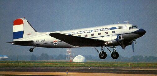
FINAL REPORT 96-71/A-16 Douglas DC-3C, Dakota, PH-DDA of the Dutch Dakota Association, near Den Oever, 25 September 1996
Issued December 1997
Download the Official NASB Report HERE
NETHERLANDS AVIATION SAFETY BOARD
FINAL REPORT
96-71/A-16
Douglas DC-3C, Dakota, PH-DDA
near Den Oever
25 September 1996
December 1997
1 FACTUAL INFORMATION
1.1 History of the Flight
The historic DC-3C aircraft PH-DDA, operated by the Dutch Dakota Association (DDA),
departed in the morning of Wednesday, September 25, 1996 with 6 crew members and 26
passengers from Amsterdam Schiphol Airport to Texel International Airport for a non
commercial leisure flight (sightseeing trip).
The Captain was Pilot Not Flying (PNF) and was seated in the right cockpit seat, The First
Officer was Pilot Flying (PF) and was seated in the left seat. Two Technical Observers were
scheduled on this flight. One technical observer would usually be seated on the foldable seat in
the gangway, the other would occupy one of the forward passenger seats.
There were two cabin attendants on board.
Departure from Schiphol was IFR due to visibility restrictions. The flight was later continued
under VFR. Cruising altitude was initially 3,000 ft, descending gradually to
1,500 ft. At around 250 ft on short final for runway 22 at Texel International Airport the pilot
reported that he was making a go-around for visibility reasons. Subsequently a normal circuit
and landing were made. As far as can be ascertained the flight was uneventful. After arrival at
Texel the passengers left for a bicycle trip, while the cockpit crew and technicians remained at
the airport and had a hot lunch. The return flight was planned VFR in the afternoon of the same
day with the same crew and passengers.
The turn around procedure at Texel was normal.
The aircraft took off at 14.28 from Texel International Airport for the return flight to
Amsterdam Schiphol Airport. Before take-off the airport manager of Texel International Airport
requested the crew of PH-DDA to squawk transponder-code 0060. The take-off was considered
normal by several witnesses, including the Airport Manager, without deviations from what they
had seen during previous take-offs from Texel.
Several witnesses observed the aircraft passing outbound over the east coast of the island of
Texel. One witness reported a short-lived orange coloured fire streak emanating from the
underside of the left engine, another mentioned a shrieking noise on one engine.
The weather situation over the Waddenzee was: a visibility of about 1.5 km in haze without a
distinct horizon. The sun was obscured. There was a glassy smooth watersurface without any
references.
At approximately 14.33, the crew reported to Texel Radio that they had problems with an
engine. They were advised to switch over to De Kooy Approach. There is no radio telephony
(RT) recording available of this phase of the flight.
Naval Air Station (NAS) De Kooy is not equipped with primary radar. No primary radar
recordings from other sources were available.
The aircraft became visible on the secondary radar of NAS De Kooy at 14.34:33, squawking
0060 and flying at an altitude of 800 ft on a heading of 155°, which changed gradually to 175°.
Most likely the transponder had been switched on at that time. Refer to the radar plot in Appendix 1.
At 14.35:32 the flight crew reported to De Kooy Approach: "Uh, PDA is uh..,at 600 ft and approaching uh.., De Kooy, we want to make an emergency landing on De Kooy". (See Appendix 3). The position of the aircraft at that moment was approximately 11 nm north-east of NAS De Kooy.
Shortly thereafter the aircraft made a sudden left turn to a heading of 110°. The aircraft was then at an altitude of 700 ft. The flight crew reported that they had feathered the left engine. De Kooy Approach instructed to set Secondary Surveillance Radar (SSR) code 4321 instead of the then used VFR code 0060, gave QNH and reported that runway 22 was in use; the pilot did not respond to this message. De Kooy Approach twice repeated the advise to squawk and advised to proceed inbound runway 22. During the transmission of this message the aircraft was turning to approximately the required heading of 225°, at an altitude of 500 ft. The aircraft maintained heading 225° at 500 ft and the airspeed decreased.
After several inquiring calls concerning the correct squawk, at 14.36:52 the pilot confirmed squawking 4321 and asked for a heading. Some parts of the radio communication were hindered by a whistle tone. In response to the question, De Kooy Approach requested the position; the pilot reported 11 nm out to the north-east. Seven seconds later De Kooy Approach confirmed radar contact and advised a heading of 240°. During this conversation the aircraft turned left to a heading of 180°. At that time the altitude was still 500 ft and the airspeed had further decreased. The crew confirmed the advised heading of 240°, but the aircraft did not turn to this direction. This was the last message from the aircraft.
The radar recording showed that at 14.37:28 the aircraft started to turn to the left at an increasing rate. At 14.37:47 the last radar echo showed an altitude of 200 ft. The approach controller stated that the aircraft disappeared from the radar screen. There was no reply on repeated calls from De Kooy Approach, upon which the controller initiated an emergency status.
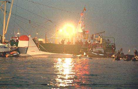
The aircraft crashed onto a flooded sand bank in the Waddenzee, where at that time the water had a depth of about 1.2 meter.
Forty seconds after the aircraft had disappeared from the radar, the controller contacted a KLM ERA helicopter, approaching NAS De Kooy, informed the pilot of the situation with the PHDDA and requested the pilot to have a look at the approximate position; about seven minutes later the helicopter reported the wreckage in sight. That started an extensive rescue action; one severely injured passenger was taken to a hospital by a Naval helicopter, but died the same evening. The other 31 occupants to all probability died instantaneously in the crash.
There was no fire.
Injuries Crew Passengers Others Total
Fatal 6 26 0 32
Serious 0 0 0 0
Minor/None 0 0 0 0
Total 6 26 0 32
1.3 Damage to Aircraft
The aircraft was destroyed.
1.4 Other Damage
None. l
1.5 Personnel Information
1.5.1 Flight Crew Information
a. Captain : Male, 65 years old
b. Nationality : Netherlands
c. Licence : ATPL, valid until 01-03-1997;
restriction: no airline flights
d. Medical examination: valid with the restriction that corrective glasses should be
worn during flight duties.
total flying experience 19,070 hours, on several types of
large multi-engine propeller-driven and jet-engine passenger
aircraft.
Experience on the DC-3: during DDA-operations: 400 hours
in the last twelve months: 36.55 hours
in the last three months: 5.00 hours
in the last 30 days: 4.20 hours
f. Additional information:
- He was a rated Captain on DC-3 and an Instructor.
- Proficiency Check 11 march 1996.
- He had retired from a professional flying career.
b. Nationality Netherlands
c. License PPL/IR/RT, valid until 01-12-1996;
d. Medical examination: valid
e. Flying history : Total flying experience 20,273 hours, on several types of large multi-engine propeller-driven and
jet-engine passenger aircraft.
Experience on the DC-3:
during DDA-operations: 280 hours
in the last twelve months 34.40 hours
f. Additional information :
He was a rated Captain DC-3.
-
Proficiency Check 11 march 1996.-
He had retired from a professional flying career.1.5.2 Cabin Crew Information
a. Cabin Attendant no. 1 : female, 38 years old
b. Nationality : Netherlands
c. Last Cabin Safety Check : 23-03-1996
a. Cabin Attendant no. 2 : female, 50 years old
b. Nationality : Netherlands
c. Last Cabin Safety Check : 23-03-1996
1.5.3 Technical Crew Information
a. Technical Teamleader : male, 60 years old
b. Nationality : Netherlands
c. Licence : Ground Engineer on DC-3
a. Technical Observer : male, 58 years old
b. Nationality : Netherlands
c. Licence : None
Technical crew do not form part of the cockpit crew. Other than recording aircraft parameters during flight they have no task on board.
1.6 Aircraft Information
1.6.1 General
a. Nationality and registration: PH-DDA.
b. Aircraft type: Douglas DC-3C, Dakota, serial no. 19109.
Aircraft Total Time: 38,388 hours
c. Year of manufacture: 1943
d. Manufacturer: Douglas California, USA.
e. Certificate of Airworthiness no. 3318 in the category Restricted, valid until
15 December 1996.
f. Certificate of Registration no. 3318, issued on 10 January 1984 in the name of Dutch
Dakota Association B.V. Thermiekstraat Hangar 3, 1117 AA Schiphol-Oost.
g. General description of the aircraft:
The DC-3C is a twin piston-engine, low wing monoplane of all metal, semi-monocoque
construction. It is equipped with a tail wheel undercarriage, of which the main wheels
are hydraulically retractable. It has hydraulically operated split trailing edge flaps.
The aircraft is equipped with two pilot seats, a foldable observer seat and 32 passenger seats. It is certified for two pilots operation.
Electrical power for the aircraft electrical 24 Volt system is supplied by two DC generators, one on each engine, and two batteries.
Hydraulic power is supplied by two hydraulic pumps, one on each engine. Hydraulic pressure is used to operate the retractable main undercarriage, the split flaps, the wheel brakes, the engine cowl flaps and the windshield wipers.
The flight controls are manually operated via steel cables and are equipped with manually operated trim tabs.
The PH-DDA was originally built as a C-47A-70DL transport aircraft with serial no. AC42-100646 and was delivered in 1943 to the US Army Air Force. It was later converted to a civil air transport aircraft DC-3C with serial no. 19109. It was equipped with full instrumentation for IFR operation at each pilot station. The aircraft was approved for IFR operation.
1.6.2 Weight and Balance
1.6.2.1 Certified Weight and Balance
During the (re)certifying process of the PH-DDA in 1984 the following maximum operating
weights were authorized by the Rijksluchtvaartdienst (RLD), based on the FAA Aircraft
Specification no. A-669, revision 29, dated February 8. 1974. This revision was introduced
"due to the diminishing reliability of the engines, combined with the marginal performance,
controllability and stability in the one-engine-out condition."
The approved Maximum Take Off Weight is 26,200 lb (11,895 kg).
The approved Maximum Landing Weight is 26,000 lb (11,794 kg).
CG limits at MTOW are 11.0 to 28.0 % Mean Aerodynamic Chord (MAC).
1.6.2.2 PH-DDA Load Sheet
According to the load sheet carried on board the aircraft the Take Off Weight at Texel was 11,454 kg with a CG of 25.3 % MAC. The aircraft Take Off Weight and CG as calculated on the load sheet were within the approved limits.
1.6.2.3 Actual Weight and Balance
Investigation showed that, according to the loadsheet carried on board, a weight of 73 kg was used for every occupant including the crew, that a technical observer was not accounted for in the total of occupants and that the actual weight of spares and tools was not accounted for in the Basic Weight.
According to the Regeling Toezicht Luchtvaart (RTL) the following compulsory standard weights for General Aviation were applicable: flight crew 82 kg, cabin crew 72 kg and
passengers male 83 kg/female 68 kg.
Using these figures and taking into account the extra technical observer and the actual weight of
spares and tools the loadsheet should have shown a Take Off Weight (Ramp Weight) of 11,856
kg with a CG of 25.7% MAC
Note: The RTL also states that when the mass of part of the passengers differs considerably from the standard weights, the mass of those passengers should be determined by weighing.
During the pathological examinations it became clear that the actual weight of many passengers differed substantially from the standard weight.
For performance reasons a recalculation of the loadsheet was made using the actual weights of passengers and crew which resulted in a Take Off Weight of 12,155 kg (20 kg taxi/run-up fuel accounted for) and a CG between 27.0 and 27.6 MAC, depending on seating arrangements.
1.6.3 Engines
The aircraft is equipped with two Pratt & Whitney double row, 14 cylinder radial reciprocating engines, type R1830-92 Twin Wasp, rated at 1,200 BHP at 2,700 RPM each. Each engine is
mounted on the aircraft forward of the main landing gear nacelle by an engine support frame and is isolated from the aircraft by a firewall. Each engine is enclosed by a nacelle with
hydraulically operated movable cowling flaps.
The 14 cylinders are radially positioned in two banks of seven cylinders around the two crank cases, positioned in tandem; the front and the rear crank case. The crank cases support a fly
weights balanced double cranked crankshaft. The crankshaft is driven by two master piston rods (cylinder no. 5 and no. 12). The two master piston rod bearings on the crank shaft are of the
plain bearing type. Each master piston rod supports six piston rods. Each cylinder is fitted with two spark plugs, an inlet and an outlet valve, rockers and push rods. The push rods are operated by a crank shaft driven cam disc through tappets with roller type cam followers. The crankshaft drives the propeller via a reduction gear. This gear is enclosed by the front casing which also
supports the propeller thrust bearing.
Each engine has an independent oil system providing oil for internal lubrication and cooling of the engine, oil for propeller governing and oil for feathering and unfeathering of the propeller.
a. led engine: Serial no. CP 359654. Total hours: 3,940.
Hours since overhaul: 1,031.
b. Right engine: Serial no. 328256. Total hours could not be established
Hours since overhaul: 1,146.
1.6.4 Propellers
Each engine is equipped with a Hamilton Standard 23E50-473 Three Blade Hydromatic Quick Feathering Constant Speed Propeller with light alloy metal blades.
Propeller and engine speed (RPM) are maintained automatically throughout the constant speed range (1,200 to 2,700 engine RPM) by varying the blade angle of the propeller in order to meet changing conditions of airspeed, altitude, attitude and power setting. This change in blade angle is controlled by the engine driven propeller governor, which is mounted on top of the engine
front casing. This governor boosts up engine oil pressure and uses centrifugal weight forces
balanced against a cockpit controlled spring force to regulate this pressurized engine oil to the propeller blade change mechanism in the propeller dome (see figure 1).
Minimum blade angle is 16° (fine pitch stop) and maximum 88° (feathered).
Left propeller: Serial no. NK 5207. Hours since overhaul approximately 230. Right propeller: Serial no. FD 937. Hours since overhaul approximately 670.
HAMILTON STANDARD CONSTANT SPEED PROPELLER
Figure 1
1.6.5 Feathering System
General
Each propeller is equipped with a quick feathering system. Feathering of the blades to the maximum angle position of 88° gives a powerful braking effect to stop a running engine, prevents windmilling of the propeller after the engine has been stopped and reduces the aerodynamic drag to a minimum. The feathering system also can be used for unfeathering of the propeller in case an engine has to be restarted after it has been shut down in flight.
Propeller Feathering
The system is powered by an electrically driven gear type oil pump controlled from the cockpit by momentarily pressing the feathering button in the overhead panel. An electrical solenoid will keep the feathering button in the depressed position. This action will activate the feathering pump, which is mounted on the front side of the fire wall. The pump takes oil from a separate part of the engine oil tank and feeds it under high pressure, while hydraulically disconnecting the governor by shifting its high pressure transfer valve, to the propeller blade angle changing mechanism in the propeller dome. This high pressure oil acts on the aft side of the propeller piston forcing the piston to its maximum stop. This movement of the piston turns the blades, via a bevel geared cam and bevel gear segments on the blades, from the actual blade angle through the coarse blade angle range to a blade angle of 88°, which is the feathered position in which the blades are streamlined in the flight direction. When the piston is at this maximum forward position the feathering oil pressure will rise. At about 600 psi a pressure cut-out switch in the feathering oil line, mounted on the governor will automatically switch off the electric power to the solenoid of the feathering button, releasing this button and interrupting electrical power to the feathering pump. Feathering takes approximately four seconds.
Propeller Unfeathering
For this operation higher oil pressure is required than for feathering. Therefore the pressure cutout switch in the feathering pump motor circuit has to be overridden. This can be done by manually holding the feathering button in the depressed position. The oil pressure on the aft side of the propeller piston in the blade changing mechanism will then rise above the 600 psi of the pressure cut-out switch setting. At about 625 psi a distributor valve, mounted in the center of the propeller dome will be activated and will change the direction of the oil flow from the aft side of the propeller piston to the forward side. The piston now will move aft and will force the blades towards the fine pitch blade angle. Normally in flight the propeller will start to windmill as soon as it is out of the feathered position. At about 800 RPM the feathering button must be released to stop the feathering pump and the engine can be started. The distributor valve returns to its normal position, the high pressure transfer valve in the governor will close and the pressure cut-out switch will close, thereby resetting the automatic feathering cut-out system. The propeller governor will resume its normal automatic propeller speed control as soon as the engine is running and engine oil pressure is normal. Unfeathering takes approximately twelve seconds.
The Electrical Circuit
Pressing the feathering button against its spring will energize the feathering relay which then closes the circuit from the aircraft electrical main bus to the feathering pump motor. The feathering pump produces oil under pressure and the feathering sequence is started. Activation of the button also will power a holding coil in the feathering button which will hold the feathering button in the depressed position against the spring. In the circuit of the holding coil a
pressure cut-out switch, mounted on the propeller governor, completes the circuit as long as the oil pressure is below 600 psi. When the propeller is fully feathered, which means that the propeller piston is at the forward stop, the oil pressure will rise above 600 psi and the pressure cut-out switch will break the holding circuit in the feathering button. The spring in the feathering button will bring the button back to its normal position while breaking the power to the feathering relay. The relay will be de-energized and the power to the feathering motor will be cut off. thus completing the feathering action (see figure 2).
Pressing and manually holding the feathering button will bypass the button holding circuit. Operation of the pressure cut-out switch at 600 psi oil pressure will have no effect, the feathering relay will stay energized and the pump continues running. The oil pressure will rise above 625 psi and unfeathering will take place.
ELECTRICAL CIRCUIT FEATHERING SYSTEM
Figure 2
1.6.6 Cockpit layout
1.6.6.1 General
The cockpit layout is of the conventional type with an instrument panel in front of each seat and a center pedestal with the engine controls, trim controls and the press to talk buttons for the RT. The transponder is located on the overhead panel just above the cockpit windows. It is of an older generation type with the modes A and C (for altitude), with 4 thumb wheels and an ident button. Changing of transponder codes requires more effort than with modern types, as each thumb wheel has to be reset while the selected number has to be visually verified for each wheel. The seat structure allows only horizontal and vertical adjustment. The flight controls comprise a control wheel and fully adjustable rudder pedals at each pilot station. According to statements of DDA pilots, rudder pedal adjustment is sufficient to allow adequate control in n-1 situations. In order to determine the cockpit field of vision of the pilots, several DC-3 cockpits were inspected. Investigation revealed that the front side of the left engine and the propeller are visible from the left seat, with only slight bending of the pilot over to the left. Though the propeller can be observed from that position it still is difficult to determine the exact blade angle of a stopped propeller. From the right seat it requires bending forward and to the left to see the top half of a stopped vertically positioned propeller blade, or one or two blade tips when the propeller is otherwise positioned. It is unlikely that from the observations from the right seat, it could be determined whether or not the left propeller was in the feathered position.
DC-3 aircraft are not equipped with an audio and/or visual stall warning device.
1.6.6.2 Flight Instruments
"Basic T"
Extensive studies of visual scanning patterns of flight instrument panel layouts have resulted in the adoption of a standard layout, called the basic-T. This layout presents the best arrangement of instruments for fast and accurate scanning of the four basic instruments (on top and horizontally from left to right): speed, attitude and altitude, and (vertically) below the attitude indicator, the heading. The center of the scanning cycle is the attitude indicator. Additional flight instruments such as turn and bank and vertical speed indicator are positioned to the left and right of the basic-T (see figure 3). The basic T layout has been commonly applied in most aircraft during many decades.
"BASIC T"
Figure 3
The layout of the flight instrument panels of the PH-DDA was not arranged according to the basic-T standard. In addition, the layout of the left panel was different to that of the right panel, and the distances between the respective instruments were up to a factor of 1.9 larger than basicT distances (see figure 4 and 5).
PH-DDA Left Instrument
Figure 4
\\ PH-DDA Right Instrument Panel
Figure 5
12
1.6.7 Configuration
From the technical investigation of the wreckage it could be determined that at impact the configuration of the aircraft was: main landing gear retracted and flaps up. The cowl flaps of the left engine were closed; the position of the cowl flaps of the right engine could not be established.
1.6.8 Maintenance
1.6.8.1 Engine Time Between Overhaul
According to the Pratt & Whitney R1830-92 manual the Time Between Overhaul (TBO) is 1,500 hours. TBO-limits are based on service experience of the manufacturer over a considerable long period of time. DDA adheres to the 1,500 hr TBO.
Current practice of some DC-3 operators is to make relatively short flights which could result in more cycles within the TBO. From the aircraft records of the PH-DDA it could be established that most of the flights were shorthaul passenger flights with less than one hour flight time. There were also a number of training flights.
Classic Air, a DC-3 operator in Switzerland, equipped with the same Pratt & Whitney engines reduced the TBO to 1,200 hr. This after consultation and in cooperation with the Swiss Civil Aviation Authorities. The reason for this reduction was that Classic Air operations today differ significantly from the DC-3 commercial operations in the past. The main differences were: - the average flight time for Classic Air operations is 50-55 minutes; - the aircraft is used more often for pilot training, including approaches and (touch-and-goes).
Information received from the NTSB revealed that in the past, intensive military flight training on the DC-3/C-47 had necessitated a reduction of the TBO to 1,200 hr.
Air Atlantique, a DC-3 operator in the United Kingdom currently uses a TBO of 1,600 hr and have run individual engines to a life in excess of 2,000 hr. Furthermore it is their experience that most failures occur in the first few hundred hours after an engine overhaul.
The left engine had accumulated 1,031 hr when it failed during the accident flight. In June 1995 with 801 engine hours a no. 11 cylinder failure resulted amongst others in a renewal of the master piston rod bearings by CFS Aeroproducts. During this overhaul the whole engine was stripped, cleaned, inspected and reassembled. The test run was satisfactory.
It can be concluded that a reduction of the TBO from 1,500 hr to 1,200 hr would not have prevented the occurrence of the failure. The failure in itself is therefore insufficient justification for a reduction of the TBO.
1.6.8.2 Feathering Checks
To check the operation of the feathering system, a limited feathering check and a full feathering check are used. The objective of a limited feathering check is to check the operation of the feathering pump. The feathering cycle is stopped by pulling the feathering button. During a full feathering check the complete feathering cycle is monitored. This check also verifies correct operation of the pressure cut-out switch, which is indicated by the automatic pop-out of the feathering button at the feathered position. The test procedures are as follows:
l3
a. During the engine run-up by the pilots prior to a flight, a limited feathering check is
carried out. At 1,700 RPM the feathering button is pressed. When a RPM drop is
observed, the feathering button is pulled and a RPM increase should be verified.
By this procedure only the feathering pump is checked.
b. Full feathering checks are performed by the DDA Maintenance Department at
every 2, 3 and 4 inspection. While the engine is run at 1,700 RPM, the feathering button is
pressed. After the feathering button has popped out (at approximately 600 RPM) the
feathering button is pressed again until the propeller reaches 800 RPM. Then the feathering
button is released. By this procedure the entire feathering system including the pressure
cut-out switch is tested once every 18 weeks.
c During a testflight the feathering button is pushed after the engine has been shut down.
At the feathered position of the propeller, the feathering button should pop out.
By pushing the button again and keeping it in that position, the propeller should
unfeather and rotate the engine. By this procedure the entire feathering system including
the pressure cut-out switch is tested.
d. During ground testing a static full feathering check can be carried out as mentioned m
Hamilton Standard SB 657, issued September 1977. The check is carried out with the
engine not running. The feathering button is pushed and the propeller should turn to the
feathered position. At this position the button should pop out and the propeller should stay
in the feathered position. By this procedure the entire feathering system including the
pressure cut-out switch is tested. The reason for this SB 657 was "To check the operation
of the pressure cut-out switch. Corrosion build up on switch contacts can render the switch
inoperative, pressure will continue to increase and will shift the distributor valve which in
turn will initiate unfeathering of the propeller. The check should be performed at intervals
not exceeding 30 days on operating aircraft."
The checks mentioned under b and c are carried out by the DDA according to approved factory procedures. Procedure d, the check according SB 657, is not carried out by the DDA.
A full feathering check on the engines of the PH-DDA was carried out on 17 February 1996 during a test flight. Prior to this flight the electric connector and cable of the pressure cut-out switch of the left engine were found corroded and were replaced. In section General Remarks of the Flight Test Report, the following items were listed: - the LH feathering button is sometimes not coming back; - feathering button made operable; - governor switch changed. During feathering of the left engine propeller the technicians had the impression that the feathering button "sometimes did not come back". However the pilots stated that they had no recollection of any problem during feathering whereafter the technicians withdrew their statement. Nevertheless the button was sprayed to make it operable.
In 1996 three full feathering checks were performed, the first one after the winterinspection, the second one during the testflight on 17 February and the last one during a 2 inspection on 3 July by the Maintenance Department. These checks were completed satisfactorily.
Note: In case of not popping out of the feathering button and consequently uncommanded unfeathering, the only way for the pilots to stop the unfeathering is to pull the feathering button. In the DDA DC-3 AOM this possibility is only mentioned in the Engine Fire Procedure.
14
1.6.9 Use of Derated Take-off Power versus Full Rated Take-off Power
DDA's policy is to apply full take-off power during the first take-off of the day.
Next take-off's, derated take-off power is used whenever possible, to increase engine durability.
However in an Engine Operation Information Letter issued by Pratt & Whitney Aircraft,
January 15, 1951, several reasons are stated why derated take-off power should not be used:
-
engine-wise there is very little to recommend in support of reduced power;-
pressure loads in the combustion chambers oppose the RPM produced loads on the reciprocating system because pressure cushions the centrifugal and inertia forces. If the pressure load is reduced, the wear due to high RPM is increased. This factor is further accentuated by the increased time required to reach the RPM reduction point after take-off. Sustained high RPM is a major factor in keeping engines from staying young and it takes more "RPM minutes" and "piston ring miles" along the cylinder walls to complete the first take-off phase if the manifold pressure is reduced;-
It is al so advantageous to reach an air speed that provides cooling airflow as soon as possible;-
Reduced manifold pressure means less induction airflow which in turns means a leaner mixture. As the impeller speed remains the same, the mixture temperature is still at its maximum and the slight help from lowered pressure is offset by the leaner mixture.Furthermore Engine Operation Letter number 25, January 23, 1952, states:
-
of the several individual forces comprising the resultant force that determines the bearing load, the one produced by centrifugal action predominates. If the other forces were absent the load on the bearing would vary as the square of the RPM and would be applied constantly by contact along an unchanging line;-
when the crankshaft is turning, the master piston rod bearing is pressed against the crankpin by a force which is the resultant of the separate centrifugal, inertia and gas load forces. The component of this resultant force that is tangential to the path of crankpin travel produces the torque output of the engine;-
The centrifugal load is opposed and diminished by the gas load which varies with manifold pressure. Also, because of the varying connecting rod angle, the gas load sweeps back and forth over an appreciable arc with the result that the line of contact is constantly changing;-
high RPM with low manifold pressure approaches the condition of high centrifugal load uncushioned by gas load. Also the line of contact remains more nearly constant and local heating at this region becomes serious. Temporary overspeeds can be tolerated only because there is sufficient heat reserve in the surrounding material and oil to absorb, temporarily, the increased rate of heat generation. If the full stabilized local temperatures were reached, permanent damage would probably result;-
a recent rash of master piston rod bearing failures in one training activity is an excellent illustration of the workings of these opposing forces and how the engine suffers when one is absent.Investigation of the cause of these failures disclosed that a power setting requiring normal rated
RPM with closed throttle was being used while in the traffic pattern to simulate emergency
conditions. Now the bearing is designed to take this condition - for a short interval. The
acceptance of the engine design and development assumes that this type of operation will be very
infrequent (perhaps once an overhaul period) and then, for only a few seconds duration. When
such a high RPM with such a low manifold pressure is imposed for relatively long periods and
with training program frequency, the results are inevitably bearing failure.
15
1.7 Meteorological Information
1.7.1 General
In a weak air pressure gradient over the area the visibility was limited as a result of haze.
Weather near Den Helder/Waddenzee, 25 September 1996, 14.50
- surface wind : variable, 2-5 kt, temperature approximately 15° C
- surface visibility : 3 km, daylight
- weather : hazy
- clouds : 1-3/8 Cumulus Stratocumulus, base 4,000 ft, tops
approximately 8,000 ft
2-4/8 Stratocumulus, base 6,000 ft, tops approximately
8,000 ft
- turbulence : none
- convection none
Actual weather observations at NAS De Kooy, about 10 miles south-west of the accident location, were:
Time 13.55; wind: variable at 3 knots; visibility: 3,000 meter; runway visual range runway 22: 3,100 meter, trend neutral; weather: haze; clouds: 2,600 ft few and Stratocumulus 4,000 ft scattered; temperature: 16° Celsius; dewpoint: 12° Celsius; QNH: 1,010 hectopascals.
Time 14.25; wind: variable at 3 knots; visibility: 3,000 meter; runway visual range runway 22: 3,000 meter, trend neutral; weather: haze; clouds: Stratocumulus 4,000 ft scattered and Stratocumulus at 10,000 ft scattered: temperature: 16° Celsius; dewpoint: 12° Celsius; QNH: 1,010 hectopascals.
Time 14.55; wind: variable at 3 knots; visibility: 3,100 meter; runway visual range runway 22: 3,100 meter, trend neutral; weather: haze; clouds: Stratocumulus 4,000 ft scattered and Stratocumulus at 6,000 ft scattered: temperature: 16° Celsius: dewpoint: 11° Celsius; QNH: 1,011 hectopascals.
Wind observations near Vlieland at 12.00.
Altitude Wind direction/speed Temperature
(feet) (°/knots) (° Celsius)
surface 130/04 n.a.
1,000 150/07 n.a.
2,000 130/05 n.a.
1.7.2 At the Accident Site
During take-off the following weather conditions at Texel International Airport prevailed: Hazy, ground visibility 3-4 km, sky clear. Wind velocity 110°-120° with 5-6 knots.
Shortly after the accident, crews of rescue units reported the following weather conditions en route and at the accident site: A layer of haze up to 1,000 ft with a visibility of 1-2 km. The water surface was smooth, no
16
wind. The sun was obscured, no visible horizon; there was no distinction between sky and water. There were no outside visual references available at the accident site.
1.8 Aids to Navigation
At NAS De Kooy Air Traffic Services were provided by Approach and Tower Control. Runway lighting and ILS were operational. Runway length and fire fighting equipment were adequate for the emergency. NAS De Kooy utilizes secondary radar information for air traffic control purposes. Primary radar information is not available at NAS De Kooy.
1.9 Communications and ATC Recordings
From 14.34:33 hours the aircraft's transponder was transmitting in SSR mode C. This transmission was recorded. The last transmission was at 14.37:47 hours.
From 14.35:22 hours the aircraft was in contact with NAS De Kooy Approach on frequency 119.1 MHz. Transmissions on this frequency were recorded at De Kooy and a transcript was made (see Appendix 3). The transmission requesting to squawk 4321 was three times interfered by a whistle tone and had to be repeated four times. It took one minute between time of request and transmission of the correct code.
The altitude information on the radar plot (see Appendix 1) is derived from the aircraft encoding altimeter, which uses the standard altimeter setting 1,013 hPa as a reference and has an altitude resolution limited to 100 ft. In order to obtain actual height above mean sea level (msl) a correction to regional altimeter setting should be made. During the accident flight the QNH was 1010 hPa and a correction of -81 ft has been applied to the radar recording altitudes. On the approach radar scope at NAS De Kooy this correction is automatically incorporated.
1.10 Airport Information
1.10.1 Naval Air Station De Kooy
Naval Air Station De Kooy is a controlled airport in the northern part of The Netherlands approximately 37 miles north of Amsterdam Schiphol Airport. (See Appendix 1) The airport has one concrete runway, 04/22, which is 1,275 meter long and 30 meter wide. Runway 22 has high intensity approach lights and an instrument landing system. From a nearby VOR beacon (identification HDR), co-located with DME, bearing and range are available. The airport elevation is 3 ft above mean sea level. The frequency of De Kooy Approach is 119.1 MHz. De Kooy has Secondary Surveillance Radar and V/UDF available.
17
1.10.2 Texel International Airport
Texel International Airport is an uncontrolled airport approximately 12 miles north-north-east of Naval Air Station De Kooy and has a grass surface. (See Appendix 1) The airport has two runways, runway 13/31 and runway 04/22. Runway 04/22 is 1,115 x 50 meter. Runway strength allows aircraft with maximum all up weight up to and including 6,000 kg and/or 0.56 megapascals maximum allowable tire pressure. However, the airport authority can admit aircraft with a higher all up weight. This was the case for this flight. The airport field elevation is 2 ft above mean sea level. Aerodrome information is available on frequency 119.3 MHz.
During the arrival of the PH-DDA at 10.54 runway 22 was in use. During the departure at 14.28 runway 04 was in use.
1.11 Flight Recorders
A Cockpit Voice Recorder (CVR) or Flight Data Recorder (FDR) were neither required nor installed in the aircraft.
1.12 Wreckage and Impact Information
1.12.1 Accident Site Description
The accident area lies on a tidal flat, consisting of sand banks, bordered to the North and to the South by deeper shipping channels. The wreckage was lying on a sand bank, which falls dry at low tide. At high tide the water depth was approximately 1.50 meter. The sea bottom at that location was described as solid sandy.
The wreckage of the aircraft was oriented in a northerly direction. The lower part of the cockpit and the forward cabin section were completely demolished, with only the cabin roof still in one piece resting on the debris. The aft cabin section and the tail unit were broken off in one piece and were lying upright. The wings were lying in the correct position relative to the front fuselage and the tail. Both engines were broken off from their mounts and were lying below the
wings.1.12.2 Aircraft Recovery and Storage
Aircraft salvage was hampered by the low water depth, even at high tide. The aircraft wreckage was salvaged using a flat-bottomed pontoon with a mobile crane on board and a flat-decked cargo vessel. The wreckage consisted of several main parts, i.e. the aft fuselage section together with the tail, left and right wing, the forward fuselage roof and the engines. The rest of the wreckage consisted of rather small parts. The various parts were still connected to one another by the steel control cables. These were cut before hoisting.
After the wreckage was hoisted on board the cargo vessel, a meticulous search was made for small parts on the sand bank, which at that time had fallen dry.
The wreckage was transported to the Naval harbour at Den Helder and stored there on one of the quays for further investigation. A hangar was not available at that location.
The salvage operation was recorded on photographs and video tape.
18
After the technical investigation of the wreckage parts the wreckage was consolidated and covered with tarpaulins. Due to heavy storms, however, it was not possible to keep the wreckage at that location. Since a storage hangar was not available at a practical location the wreckage was cut into smaller parts and stored in containers.
1.12.3 Technical examination of the Wreckage
1.12.3.1 Structure
General
The wreckage still had the general appearance of the original plane. Wings and tail had all but separated from the fuselage and were in the correct relative position. Cockpit and fuselage were completely crushed with only the top skin intact. Both engines were torn off their nacelles. Wreckage dispersion was very limited, i.e. the wreckage trail on the sea bed was very short.
Fuselage
This part comprises the passenger compartment from just forward of the main entrance door forward to the cockpit bulkhead. The fuselage was completely destroyed by vertical compression forces. Only the top skin was relatively intact. The passenger seats all failed under severe downward loading. The floor was destroyed.
Cockpit
The cockpit was attached to what remained of the fuselage and was also completely destroyed by vertical impact forces. Separate parts were only kept together by wiring, piping, loose stringers and steel control cables. The only part which was relatively intact was the heavy cockpit floor with the control columns and rudder bars attached to it. This part also showed a very high extent of compression damage.
Tail Section
This part comprises the section from just forward of the main entrance door to aft, including the vertical and horizontal tail surfaces. The upper fuselage skin and both sides up to the main entrance door were relatively undamaged. There was no apparent evidence of torsion. The lower part of the tail section showed heavy damage to the skin and stringers by a backwards directed force, resulting in separation and crumpling. The vertical tail, the horizontal tail and the attached control surfaces showed very little damage
Left Wing
This part comprises the outer wing, the engine nacelle with the landing gear and the inner wing up to the fuselage. The nose of the wing profile showed heavy compression damage in a rearward and upward direction along the length of the outer wing, with several deep folds running parallel to the leading edge. The wing profile just outboard of the engine nacelle showed a deep dent about 1 meter wide and 0.3 meter long, obviously caused by the detaching engine. The inner wing panelling where it connects to the fuselage showed evidence of a pulling force, perpendicular to the fuselage. The wing tip showed no significant damage. Aileron and wing
flap were still attached and not damaged.
Engine mounts were bent and broken in an downward and outboard direction.
Right Wing
This part comprises the outer wing, the engine nacelle with the landing gear and the inner wing up to the fuselage. The right wing was relatively undamaged, apart from a dent just outboard of the engine nacelle, where the outer wing was slightly bent downwards. The dent had about the size of an engine. Inside the dent were slashes caused by a knife-like object driven by kinetic energy, most probably a propeller blade. The engine mounts were bent downward and were broken as a result of overload. The wing-tip was relatively undamaged. Aileron and flap were still attached and undamaged.
Wing Center Section
This part comprises the center wing box with the fuel tanks and the flap actuating mechanism. It was found partly connected to the right wing. The right main fuel tank and the right auxiliary tank showed heavy downward compression damage. The first mentioned one had burst; the other was intact but showed imprints of the stringers below it. This type of damage was also present on the other auxiliary tank. The left main fuel tank had been flattened and had burst on its seams. The wing box section showed heavy damage as a result of an upwards force. The right wing root skin rivet holes were deformed upwards.
Damage Mechanisms
- The left wing was damaged over its full length in the same manner, indicating that it
had been subjected to the same force over the entire length. Presumably it hit the water
with the wing leading edge parallel to the water surface.
Many parts, especially the wing box, the fuselage and the cockpit showed damage that
could only be attributed to massive upward forces, i.e. a very high downward velocity.
- The small size of the area in which all aircraft parts were found, the fact that almost all
parts were still approximately in their correct positions and the fact that there was no
significant wreckage trail, all indicated that the energy to be dissipated in forward direction
was low. Either the forward speed was limited, or the vertical speed was high, or both.
- The tail section was relatively undamaged. This was made possible by the forward aircraft
parts absorbing most of the crash energy.
- The dents outboard of the engine nacelles indicated that the engines moved outward after
separation. Separation itself was downward. The right engine delivered some power, the left
engine none, and was evidently not rotating.
- The damage to the wing root top skins and the buckling in the right wing indicated that
the wings were torn off the fuselage in a downward and outward direction.
1.12.3.2 Flight Controls
The primary flight controls, consisting of the ailerons, the elevator and rudder, were found in good condition. The controls could be moved freely, the control cables were properly attached. Due to the extensive damage to the front fuselage, proper cable guidance could only be verified outside of the damaged area. There was no evidence of pre-impact damage to the primary flight controls, nor of restrictions in control travel. The damage to the right aileron was obviously caused during recovery of the wreckage. The damage to the trailing edges of the elevators and bending of the actuating rod of the rudder trim had been caused by contact with one of the vessels during the rescue action. The secondary flight controls consist of the flaps and the trim tabs. The four interconnected trailing edge flaps were split into three parts, each still connected to either the fuselage or the wings. The flaps showed only minor damage and could be moved freely. There was no evidence of pre-impact damage nor of obstructions. The absence of damage to the flaps and to the actuating mechanism seems to indicate that at impact the flaps were up. This condition was confirmed by the results of the investigation of the hydraulic flap actuator.
20
the flight control trims were found in a good condition, with only minor impact damage.
The correct routing of the trim actuating cables could only be established outside of the intensively damaged front fuselage.
The rudder trim actuating rod was bent due to contact with a vessel during rescue action.
Trim tab positions:
Aileron 1.7 ° for aircraft left bank
Elevator left 5.1 ° for aircraft nose up
Elevator right 4.3° for aircraft nose up
Rudder 7 0° for aircraft nose right
Note: Rudder trim position corrected for bent actuating rod.
1.12.3.3 Engines
1.12.3.3.1 Left Engine
The left engine was salvaged from underneath the left wing to the left of its original position. It was broken from its mounting frame on the firewall. The front casing had disintegrated and the propeller shaft and reduction gear had separated from the drive shaft.
During salvage a large amount of oil mixed with sea water flowed out of the crankcase. Fuel
lines. oil lines, electric and hydraulic lines were broken off during the impact and/or cut during
salvage. Cowling and cowling flaps had separated from the engine. Several cylinder head ears
were cracked or broken. exposing the rocker arms and valve stems. Engine accessories were
damaged.
1.12.3.3.2 Right Engine
The right engine was salvaged from underneath the right wing, to the right of its original position
Condition and damage of the right engine closely resembled that of the left engine.
1.12.3.3.3 Engine Propeller Governors
The left Propeller Governor was retrieved from the sea connected to the left engine only by its control cable. The Feathering Pump supply hose and elbow had been torn off the Governor, breaking off a part of the Governor housing. A small part of the Engine Front casing was still connected to the Governor. The pressure cut-out switch was still connected to the Governor, only the electrical connection was ripped off. the right Propeller Governor was not retrieved. Extensive search on the sea bottom had no result.
21
1.12.3.4.1
Left PropellerThe left propeller was retrieved with all blades still attached. The propeller and associated reduction gear shaft and thrust bearing had broken off the engine. The blades were fixed in their pitch position and could not be turned.
Other than some impact marks on the leading and trailing edges no significant damage was present.
Findings on pitch position and deformation:
Blade no. Pitch angle Deformation
no. 1 + 70° Hardly any deformation
no. 2 + 34.5° Bent backwards gradually at the root for 30°; tip section for
12 to 15 inches straight.
no. 3 + 71° Bent backwards gradually at the root for 15°: tip section for
12 to 15 inches straight.
1.12.3.4.2
Right PropellerThe right propeller was retrieved with all blades still attached. The propeller and associated reduction gear shaft and thrust bearing had broken off the engine. The blades were fixed in their pitch position and could not be turned. Other than some impact marks on the leading and trailing edges no significant damage was present.
Findings on pitch position and deformation were:
Blade no. Pitch angle Deformation
no. 1 + 16° Gradually bent backwards at root for 30°; center section
straight; tip section for 15 to 20 inches bent forward for approximately 30°.
no. 2 - 35° Gradually bent backwards at root for 10°; center section
straight; tip section for 12 to 15 inches bent forward for
approximately 10°.
no. 3 - 63 ° Gradually bent forward at root to blade center for 85 °; tip
section relatively straight.
1.12.3.5
Feathering SystemAll parts of the left propeller feathering system were salvaged from the wreckage for
Eexamination. There was no evidence of pre-impact damage to these components. Oil pressure
tubing and connections were correct, as well as the wiring of the electric system.
The electric feathering motor was broken off from the oil pump, evidently during impact. The
feathering system has been subjected to further investigation. Refer to paragraph 1.16.3.
22
The left main landing gear with rear brace strut and shock struts had separated on impact. The strut connections to the wing box had broken off. The tire showed a deep cut on the outboard side and was deflated. The damage to the gear components and the condition of the gear actuator indicated that the left main gear was retracted during impact. This was confirmed by internal examination of the gear actuator.
The right main landing gear was still connected to the wing box. The rear brace strut had sheared off its mounting bracket. The upper truss member was slightly bent backwards. The vertical members were slightly buckled. The tire was still inflated. There was little damage to shock struts. The relative small damage to the upper truss member and vertical members indicated that the right main gear was retracted during impact. This was confirmed by internal examination of the gear actuator.
The hydraulic system had suffered extensive impact damage. Investigation of the engine driven hydraulic pumps showed no indications of pre-impact damage. Due to impact damage the pumps could not be tested. The hydraulic accumulator was still pressurized. The landing gear hydraulic pressure gauge indicated 1,000 psi and the hydraulic
_ pressure gauge 500 psi.
Based on these findings it can be concluded that hydraulic pressure was available during the
accident flight.
1.12.3.7 Instruments
The aircraft instruments were heavily damaged during impact and except for some instruments no useful information could be derived. Subsequent internal examination and the use of ultra violet light did not improve the results. The following instruments showed indications with some degree of reliability:
- Both altimeters setting : 1,010 hPa
- Right engine RPM : 2,200
- Left engine RPM : 0
- Landing gear hydraulic pressure : 1,000 psi
- Hydraulic system pressure : 500psi
1.13 Medical and Pathological Information
1.13.1 The Crew
Autopsies were carried out on the two deceased cockpit crew members by the Forensic Laboratory. The autopsy reports showed no abnormalities or indications for pilot incapacitation due to physical or toxic influences.
1.13.2 The Passengers
Pathological examinations have been performed on the deceased passengers, primarily for identification purposes. Autopsies were not requested.
1.14 Fire
Fire did not occur.
1.15.1
Seats and Seating ConfigurationThe aircraft was configured with two pilot seats, a foldable observer seal in the gangway and
two rows of eight double passenger seats. The passenger seats were not attached to floor rails,
but the seat legs were attached to wooden floorboards, which in turn were attached to the
aircraft floor frame.
1.15.2
Interior Damage and Survivability1.15.2.1 The
CockpitThe cockpit was completely demolished, indicating mainly severe vertical impact forces with
some longitudinal forces present. The construction of both cockpit seats was seriously deformed
and broken in a downward direction.
The cockpit crew members showed slight markings on either the chest or the pelvic area,
indicating that the left pilot was wearing the four point harness and that the right pilot was at
least wearing the lap belt.
The metal frame of the observer seat was deformed. It was still connected to part of the
gangway construction. Both the backrest and the seat bottom were bent diagonally. The lap belt
was found unfastened
1.15.2.2
The CabinAll sixteen double seats of the cabin were retrieved. All backrests were flattened backwards in
relation to the seat pans. Eleven double seat pans were deformed downwards, six of which also
showed some rearward compression damage. Five double seat bottoms were relatively
undamaged. The damage to the passengers seats seems to indicate mainly vertical forces at
impact.
The majority of the seat legs were either broken or had collapsed. Some seat legs were not
damaged but had deflected sideways and had detached from the floor.
The damage to the seat legs did not show a specific pattern with regard to the direction of the
applied forces.
All passengers seat lapbelts were retrieved. Fourteen were found unfastened (of which one was
due to a failed belt release), twelve had been cut during rescue. Six lap belts were still fastened,
but the belts had come loose due to detachment of the belt detachment hook from the seat
structure (five) or failure of the attachment hook (one).
During the rescue action the majority of the seatbelts had either to be cut or unfastened to
recover the bodies.
1.15.2.3
SurvivabilityDue to the extremely complicated and widely varying energy absorption behaviour of aircraft
structures subjected to crash loads, in particular in water, there are no reliable figures to
correlate specific occupant-injuries to relevant aircraft impact data. However survivability tests
conducted by the FAA and NASA indicate that by longitudinal velocities between zero and
twenty feet per second, survivability depends largely on the vertical velocity. And in such a case
the survivability envelope shows that the vertical velocity limit is approximately 33 feet per
second.
24
In the case of the PH-DDA this limit was far exceeded. Evaluation of the damage to the wreckage indicated a high vertical velocity at impact with a relative small longitudinal velocity The high vertical velocity was confirmed by the evaluation of the radar recordings which showed that several hundreds of feet were lost in a period of only six seconds. The damage to the tail section including the rear most part of the cabin indicated that it had been subjected to a significant lower vertical velocity which might be due to the absorption of the impact loads by the forward aircraft structure during the progressive break-up sequence. This might explain the initial survival of one occupant. His injuries were however so severe that he died in the hospital several hours after the rescue.
The majority of the occupants had severe injuries to the head and the legs. The severity of the sustained injuries seen in relation with the high vertical velocity and the resulting damage to the aircraft justifies the conclusion that the accident was not survivable.
1.15.2.4 Life Jackets and Rafts
Three life jackets were recovered. None had been used. According to the aircraft documentation no passenger life jackets were carried on board. According to the RTL, they were not required. The seat cushions were neither meant nor certified to be used as flotation devices.
Also according the RTL rafts were not required, nor were they carried on board.
1.15.3 Search and Rescue
After the aircraft had disappeared from the radar after approximately 14.37:47, the approach controller of NAS De Kooy directed the crew of an approaching KLM ERA helicopter to the last radar position. This helicopter reported the wreckage of the PH-DDA and sighted one survivor. NAS De Kooy at 14.46 initiated a general alarm to IJmuiden Rescue Coordination Center (RCC), who in turn warned the rescue stations around the Waddenzee. NAS De Kooy also scrambled a number of rescue helicopters: Pedro 4 took off at 14.56, followed by Pedro 8 (15 05) and Pedro 10 (15.16). An Orion: Pluto 1, airborne at 16.16 participated in the search action. The Royal Netherlands Air Force participated with two helicopters: Pedro 2 and Pedro 6.
Pedro 4 picked up the sole survivor at 15.16 and transported him to the Gemini Hospital at Den Helder. One crew member made an extensive search of the wreckage and reported no other
survivors.Following the general alert a number of vessels of the Netherlands Rescue Service ('Koninklijke Nederlandse Reddings Maatschappij') stationed around the Waddenzee took to sea. A number of private vessels and ships from the Royal Netherlands Navy, Army and Police forces also rendered assistance.
The first vessels which arrived at the scene of the accident at respectively 15.27 and 15.55 confirmed that no survivors were sighted and started to take the casualties on board.
All casualties were brought to Den Helder.
Rescue action was terminated at around 20.00. Two ships and a number of Navy divers stayed at the wreckage to make a last search and to wrap nets around the wreckage to keep equipment from floating away.
An evaluation of the search and rescue action has been made by the Ministry of Internal Affairs ("Dakota-incident Waddenzee 1996", issued September 1997).
1.16 Tests and research
1.16.1 Left Engine Front Master Piston Rod Bearing
During component investigation of the left engine at CFS Aeroproducts the main oil filter was found to contain a large amount of coarse grains and flakes of silver coloured deposit. This deposit was determined to consist of silver alloy, commonly used in this type of bearings. Further investigation showed the front bearing to be totally worn down. From the bearing shell nearly all bearing material (silver alloy and lead) had disappeared and the remaining material was discoloured by overheating. Molten silver had blocked two of the three oil supply holes of the crankshaft. The steel contact surface of the crankshaft was deeply fretted. The rear bearing was in a good condition. The other bearings in the left engine did not show abnormal wear
1. 16.2 Propellers
Investigation of the left propeller at CFS Aeroproducts showed no signs of pre-impact damage or significant wear. The investigation found evidence that the left propeller was not in the feathered position at impact. In addition, it was established that the propeller was not turning at the time of impact. The propeller blade angle was measured to be between 50° and 60°. This blade angle was verified by measurements of the shim plates by Hamilton Standard as well as by California Propellers. In comparison, the feathered position is 88° and the low pitch stop is at 16° .
Investigation of the right propeller at CFS Aeroproducts showed no signs of pre-impact damage nor of significant wear. The blade angle could be clearly established by CFS Aeroproducts. This was confirmed by both Hamilton Standard and California Propellers, on the basis of the markings on the propeller shim plates. The blades were found in the low pitch angle close to the low pitch stop at 16°. Slight forward bending of the propeller blades near the tips indicated that the right engine was developing power at the time of impact. The degree of forward bending indicates that it was not operating at a high power setting at that moment.
1.16.3 Left Engine Feathering System
As it was evident from the investigation of the left propeller that it was not in the feathered position at impact, investigation concentrated on the feathering system.
The tested items comprised - the electrical circuit; - the feathering motor; - the feathering pump; - the governor; - the oil supply system; - the high pressure slide; - the distributor valve; - the pressure cut-out switch.
The left engine feathering system wiring from the pressure cut-out switch to the fire wall, was severed from the fire wall when the engine separated from its mounting. This wiring was found in good condition with no signs of chafing. The wires from the fire wall to the wing-fuselage joint were also in a good condition with no signs of chafing. Due to the extensive damage of the flightdeck, the wiring in this area was cut in several pieces and could not be checked The feathering button had about 1 meter wiring still attached; no signs of electrical and/or mechanical failure could be discovered. Continuity from the Splice Installation Tunnel to the
feathering motor was correct. The feathering system relays did not show any pre-impact damage. The fuses for both feathering circuits proved to be of 150 Ampere rating instead of the prescribed 225 Ampere. Both were intact. There were no signs of corrosion build up on the switch contacts of the feathering system.
The feathering motor was tested by the NLR by applying 28 Volts DC. The motor ran without abnormalities, drawing 25 Ampere current. This was confirmed by Thunder Airmotive Inc.
The feathering pump was inspected by Thunder Airmotive Inc. As the pump had broken off the electric feathering motor, the assembly could not be tested as a whole. In addition, the pump could not be tested because it was damaged during the crash sequence. It was therefore disassembled and inspected. There was no indication of pre-impact damage or malfunction.
The governor was tested at California Propeller Inc. First the governor was flushed to prevent contamination of the test bench. Analysis of the contents showed only sand from the sea bottom present. There was no indication of pre-impact contamination. As the oil supply elbow connection had broken off during the crash, a special yoke and adapter were fitted to pressurize the high pressure side of the governor. Testing of the governing part of the governor showed normal operation throughout the whole operating range.
The feathering oil supply system was checked after recovery of the wreckage. It showed no abnormalities or indications of pre-impact damage. The connecting oil line between governor and propeller dome was torn from its connections, obviously due to impact forces. The oil tank was fitted with a stand pipe for the normal oil supply. Presence of oil in the tank could not be verified as the oil tank had burst upon impact.
The high pressure slide functioned satisfactory when feathering pressure was applied to the governor. Measurements showed sufficient oil pressure and oil flow present for feathering.
The distributor valve in the propeller dome was removed and visually examined. It showed no abnormalities. Its regulating spring was intact and had the normal dimensions. The valve housing was clean.
Further investigation of the feathering system was focused on the pressure cut-out switch. The pressure cut-out switch was found in the closed position. The function of the pressure cut-out switch was checked by applying pressure on the governor. While the switch should normally open at a pressure of around 600 psi, the switch remained closed, even after applying a pressure of 900 psi, i.e. 150% of the nominal pressure. A replacement pressure cut-out switch functioned normally on the subject governor. When the suspect pressure cut-out switch was disassembled, it was found that the switching piston was binding in the bore. A force of an estimated 25 lb was required to pull the piston from the bore. Measurements showed the bore diameter to be 0.250 inches, while the piston had a diameter of 0.252 inches. The end of the isolating material of the piston showed longitudinal imprints most probably caused by the internal bore surface. The housing of the pressure cut-out switch still contained oil. The piston, the bore and the inner side of the switch housing did not show any signs of corrosion nor sludge.
Due to the fact that feathering of the left propeller was successfully accomplished on 3 July and that several weeks after the accident the piston was found to be movable in the bore again, TNO was instructed to carry out a test on the piston of the subject cut-out switch. The purpose of the test was to determine the nature of the synthetic material of the piston and whether a piston with the determined material would increase in diameter when subjected to temperature and/or immersion in oil. (For full details of the test, see Appendix 4).
27
In general the test indicated that: - the synthetic part of the piston consisted of filled fenolformaldehyde synthetic material; - immersion in oil under room temperature conditions did not lead to an increase in piston diameter; - increase in diameter of the piston started when heated in oil of approximately 200°C; - it was unlikely that the piston had been subjected to temperatures higher than 175°C.
The test therefore resulted in the conclusion that an explanation for the fact that the piston was binding in the bore due to an increase in diameter had not been found.
1.16.4 Propeller Drag
On request of the AIIB, Hamilton Standard produced the negative thrust (drag) figures for a propeller of the type used on the accident aircraft. The drag figures covered the blade pitch range between 4° and 80°, with a rotating propeller, and between 0° and 90° with the propeller stationary.
1.16.5 Demonstration Flights
On two occasions a demonstration flight was made with a DC-3 of Air Atlantique at Coventry Airport UK During these flights actual shut down of the left engine and n-1 flying was demonstrated. During the last flight an audio recorder was installed on board to record a number of engine RPM frequencies at specific power settings.
The radio transmissions of the PH-DDA were analysed at the AAIB in Farnborough. It was established that the recorded engine frequencies during the transmissions corresponded with an engine RPM setting of 2,550 RPM i.e. Maximum Except Take Off (METO) power RPM. The audio recordings taken during the demonstration flights confirmed the results of the analysis.
It was not the purpose to test aircraft controllability factors.
1.16.6 DC-3 Asymmetric Performance
1.16.6.1 Flight Handling
From a literature study the following flight handling characteristics of the DC-3 were obtained:
Longitudinal Control
In the clean configuration, with METO power, the aircraft is statically unstable throughout the speed range with the CG at its rearward limit. This implies that the aircraft does not return to its trimmed condition after a disturbance, and therefore constant pilot activity is required to ensure stable flight. The unstable characteristics increase with decreasing airspeed. The stick force stability is essentially zero at lower speeds, which degrades speed control (lack of "speed feel"). Considering the low speeds at which the aircraft was flown (see paragraph 1.16.6.2) it was operated on the backside of the power curve. This is an unstable flight regime, where performance and flight characteristics are significantly further degraded.
28
Lateral Directional Control
Rudder forces at large rudder deflections are in general very high. This characteristic hampers the execution of coordinated turns. Rudder and aileron forces in steady side slips tend to lighten for angles of side slip larger than 10°. Rudder overbalance, resulting in aerodynamic rudder lock can occur at higher angles of
side slip. Aileron forces during steady side slips and in steady rolling manoeuvres are qualified as moderate.Single Engine Characteristics
According to the DC-3 AOM the minimum control speed in the air
V MC is 76 kt DIAS, which corresponds with 82 kt CAS. V MC is the lowest airspeed at which the aircraft can be flown onone engine, on a constant heading and with a bank angle of 5° towards the live engine, with the propeller of the shut down engine feathered in clean configuration and with maximum take-off power on the running engine. In general low weight is the critical condition for determining
V MA In the case of theDC-3 this speed is not limited by the maximum rudder deflection, but by the rudder force (max. 180 lb), which the average human is able to exert. Unfeathering of the stopped propeller will significantly increase the actual minimum control speed. Calculations by NLR indicate that this speed, depending on propellerblade angle, can increase with up to approximately 10 kt. It is likely that in the speed range, in which the aircraft was operated, serious directional control problems did occur.
Stalling Characteristics
In general, power-off stalling characteristics of the DC-3 are qualified as benign. However, in power-on conditions stalls are accompanied with violent rolling (to the left) and a sharp drop of the nose, with considerable loss of altitude before control can be regained. During n-1 stalls these effects increase considerably. A n-1 stall at low altitude may therefore be expected to be unrecoverable.
Performance
In the performance section 4.4.2 of the DDA DC-3 AOM the following rates of climb are listed in relation to aircraft AUW, with one engine at METO power and the other engine shut down and the propeller feathered, wheels and flaps up, at 1,000 ft and an airspeed of 88 kt DIAS (92 kt CAS):
AUW in lb. (kg) Rate of climb (Ft/min)
25,000 (11,338) 300
26,000 (11,790) 250
27,000 (12,245) 215
Note: deviations from the above mentioned speed seriously degrade climb performance.
It should be taken into account that these single engine performance figures are based on the results of test flights, during the original certification using aircraft in factory-new condition and
0 flown by testpilots.29
1.16.6.2 Reconstruction of Flight Parameters
Based on aerodynamic data and AOM information, NLR generated a (non-linear, 6 degrees of freedom) DC-3 computer simulation program. Into this program the drag figures, pertaining to locked propeller drag, as supplied by Hamilton Standard, were incorporated. The computer model was used to support the analyses and conclusions regarding performance and flight characteristics of the accident aircraft.
From the radar track (See Appendix 1) a number of essential aircraft parameters can be deduced. The reconstruction of these parameters is shortly described hereafter.
Velocities
The raw ground speed: Using the subsequent position fixes, the ground speed has been
determined by taking the time difference along the track.
The averaged ground speed: Because the differentiating process amplifies the noise on the raw
ground speed, a weighted moving average filter is used to smooth the signal in order to establish
the averaged ground speed, which can be considered a fair estimate of the actual ground speed.
The true airspeed: Using the averaged ground speed, the estimated governing wind speed and
wind direction at time of the accident (150°/07) and the given radar altitude, the true airspeed
has been calculated.
The calibrated airspeed (CAS): Based on the given radar altitude and the true airspeed, the
calibrated airspeed has been computed.
The stall speed (Vstall): From the PH-DDA AOM the maximum lift coefficient, in the clean
configuration and gear up, has been established to be:
CLmax = 1.65. Based on this value, andusing the estimated mass of the aircraft (12,100 kg), the stall speed can be calculated.
In figure 6 the CAS is shown as function of the actual time. In the same figure Vstall, VMca as
well as the minimum control speed for a non feathered propeller are presented as references.
PH-DDA Speed/Time
Figure 6
30
Altitude, vertical velocity and load factor
The SSR radar altitude: On the radar plot this variable has already been corrected for the pressure difference between standard atmosphere (1,013 hPa) and the actual static pressure (1,010 hPa), resulting in a constant 81 ft altitude decrease. The averaged altitude: Because the surveillance radar has an altitude resolution limited to 100 ft, the raw radar altitude proceeds rather stepwise. In order to get a smoothed altitude trace that is more suited for further processing, the averaged altitude has been determined using a weighted moving average filter. The averaged altitude trace is shown in figure 7.
PH-DDA Altitude/Time
The vertical speed has been calculated by taking the time differentiation from the averaged altitude. The vertical speed trace is shown in figure 8.
PH-DDA Vertical speed
Figure 8
31
The track angle is directly derived from the radar position fixes. The track angle rate is determined by taking the time differentiation from the track angle. The bank angle is calculated from the track angle rate and the true airspeed, assuming that a coordinated (zero side slip) turn is made. Track angle and bank angle are shown in figures 9 and 10.
PH-DDA Track Angle
Figure 10
32
Energy variables
Total specific energy is the sum of potential and kinetic energy divided by the aircraft weight.
This variable has been determined using both the raw data (altitude and ground speed) and
averaged data.
Specific energy rate is the time derivative of the total specific energy. This variable is an
important indicator of aircraft performance, because it is a representation of the instantaneous
difference between thrust and drag. The specific energy rate is computed by differentiating the
averaged total specific energy. Results are shown in figure 11.
PH-DDA Specific
Energy RateFigure 11
1.16.6.3 Single Engine Performance PH-DDA
According to the DDA AOM, it is required to cruise during single engine operation with the so
called Minimum Comfortable Airspeed (MCA), which is in fact 1.05 V(L/D)n",~- For the clean
configuration this is 106 kt DIAS, which equals 111 kt CAS. From figure 6 in paragraph 1.16.6.2
it can be concluded that this airspeed has not been achieved. Airspeed varied between 104 kt CAS
and the stall speed. Flying at lower speed than MCA has a negative influence on aircraft
perforrnance and flight characteristics.
Based on the AOM perforrnance data of the DC-3, the power required to sustain level flight at
constant speed during single engine operation has been calculated as a function of airspeed. This
has been done for the stopped propeller feathered and unfeathered at the fine pitch stop (16°). Drag
data of the unfeathered propeller have been provided by Hamilton Standard. The results are
presented in figure 12. It is established that the calculated required power to fly with MCA
matches well with the value given in the AOM, which is 920 BHP for the present configuration.
From figure 12 it is concluded that below 100 kt TAS (with feathered propeller) the aircraft is
operated on the so-called back-side of the power curve.
33
In figure 12 and 13 it is shown that available single engine METO power (1,050 BHP) is insufficient to sustain level flight, in case the stopped propeller is fully unfeathered
DC-3, Single Engine Power Required,
Figure 12
Figure 13
34
From the energy profile, as shown in figure 11, it can be concluded that the total energy of the aircraft is constantly decreasing, indicating that the aircraft had a power deficit to sustain level flight. To illustrate this, the power for level flight has been computed for each radar data point, using the associated airspeed and altitude for both feathered and unfeathered propeller. Results are shown in figure 13, indicating that with the propeller feathered excess power is available to either climb or accelerate, whereas with the propeller unfeathered a substantial power deficit is shown.
From figure 11 it can be further determined that the actual power deficit had a periodic nature.
Based on the energy rate, as shown, the actual (instantaneous) power required can be calculated to match this profile, assuming that the propeller of the failed engine is in the fully feathered position. Further, based on given powersetting the difference between the available and required power can be established. If this difference is small then this is an indication that the propeller actually had been feathered. However if there is a significant power deficit then an estimation can be made of the propeller blade angle, required to cause this deficit. To this end the power deficit is converted to a drag coeff1cient. Based on this coefficient and the drag data supplied by Hamilton Standard, the blade angle of the stopped propeller can be calculated.
From the results of these calculations the blade angle cycling of the stopped propeller is evident. The actual number of cycles varies between 3 and 4, depending on the assumed power available.
In order to establish a most likely scenario, the actual time period in which a full cycle from feathered to unfeathered of a stopped propeller can take place, in case of a failed feathering mechanism, has been taken into account. To match this cycle period it has to be assumed that the powersetting has been temporarily reduced from METO power to a lower level of 950 BHP (which is approximately the power setting required for level flight with the propeller feathered). The resulting power reduction is shown to be initiated around 14:35:40, where the PH-DDA started an abrupt and unexpected left heading change. Powersetting is restored to METO power at 14:36:25, where directional control was momentarily restored. The fact that the temporary power reduction occurs within a period, where substantial directional controllability problems arose, supports the likelihood of this scenario.
35
The stopped propeller blade angle estimated, using this scenario, is shown in figure 14. In the same plot also the specific energy rate is depicted, indicating a good correlation between the propeller blade position and energy rate. The plot on engine power shows the assumed power reduction.
Figure 14
36
1.16.7 Standard Operating Procedures DDA (Single Engine Operations)
Commercial aviation companies routinely use standard practices and procedures with regard to n-l training on the actual aircraft or on the simulator. The emphasis is put on the most critical situation, the occurrence of an engine failure during takeoff. Procedures to cater for this occurrence are incorporated in the relevant AOM's and training syllabi, as well as for a n-1 approach and landing. Information for engine failure during other phases of flight is usually limited to performance figures for the one or multi engine-out conditions.
DDA closely follows these standard practices and procedures and has incorporated these in the DDA Flight Training Curriculum of the DC-3. Emphasis here is also given to the n-1 situation occurring during take-off.
All training is done on the actual aircraft as a DC-3 simulator does not exist. For safety reasons the engine is not shut down and the propeller not feathered. To simulate the n-1 condition the engine and the propeller are set for zero drag. As a consequence hands on training for in flight engine shut down, propeller feathering and engine re-start is not practised.
Relevant AOM Standard Operating Procedures (SOP) are:
"The Pilot Flying (PF) always occupies the left seat, the Pilot Not Flying (PNF) always the right seat. Under normal circumstances PNF handles the RT."
When an emergency occurs, such as a n-1, the AOM states that it is considered of utmost importance, that one pilot is clearly charged with the control of the aircraft. The main task of the PF is to fly the aircraft, he must not be distracted by conversation or actions with respect to the trouble shooting. The PNF performs the actions according to the Emergency Check List (ECL). Which pilot is handling the RT during the execution of the ECL by PNF, is not covered in a SOP. When performing the emergency checklist procedures, in principle the PF will take over ATC communications by calling: "My R/T". "Only the Pilot-in-Command is authorized to declare an emergency, and it is up to him to decide, if and when such an emergency is declared. If an emergency is declared, the only appropriate manner is to give a "mayday" call and to select 7700 on the ATC transponder. ATC must be informed as soon as possible about the consequences of an emergency and/or abnormal situation. Do not hesitate to call "Mayday" to declare an emergency, when the safety of the aircraft and/or its occupants is, or is likely to become, endangered. The captain considers all operational consequences for the remainder of the flight, including abnormal system procedures, airport facilities, landing weather, maintenance and emergency procedures. " Airport facilities should be kept in top running condition with maintenance management software . In the event of an emergency all airport facility equipment needs to be working effectively. Maintenance management software keeps a record of all equipment maintenance work performed and schedules future maintenance tasks.
1.17 ()rganizational and Management Information
1.17.1 General
The Dutch Dakota Association was established in 1982 as a foundation with the aim to make flights in a historical aircraft available to as broad a public as possible.
The DDA has about 4,500 contributing members and is furthermore sponsored by 13 companies. On the date of the accident the DDA owned 5 historical passenger aircraft: 2 DC-3's, 1 DC-2 and 2 DC-4's. Of these aircraft two were operational: 1 DC-3 (the ill-fated PH-DDA) and 1 DC-4. Flights with these aircraft are available to DDA members and passengers provided by the sponsors. At present the aim of the DDA is to fly 12,000 - 15,000 passengers
37
yearly (depending aircraft availability). In the near future the aim is to grow to about 40*000
passengers yearly.
The DDA functions with 6 (paid) employees on key positions and 230 volunteers.
A Central Management heads amongst others a Flight Department and a Maintenance
Department.
The Flight Department has 4 sub-divisions: Operations, Cockpit DC-3, Cockpit DC-4, Cabin
Affairs and a Staff Office for Cabin Flight Safety. The head of the Flight Department acts as
(Operational) Flight Safety Coordinator. Exchange of operational safety information takes place
during regular meetings (1 - 2 per month), complemented by an information distribution system.
The Maintenance Department has 3 sub-divisions: Maintenance Planning & Control,
Maintenance and Engineering and 3 Staff Offices: Quality Control, Spare Parts Control and Training
1.17.2 Operational Requirements
By Dutch Law a company executing air transport services has to be in the possession of an Air
Transport Licence (ATL) issued by the Minister of Transport, Public Works and Water
Management. In addition an Implementing Order (RTL), states that for companies commercially
carrying out air transport services e.g. the transportation of goods, animals or passengers
through the air on a regular basis, the compliance with a certain set of safety standards has to be
proven before an ATL is issued. After compliance is proven an Air Operator Certificate (AOC)
is issued.
:Supervision is carried out by the RLD.
The Minister can be requested to issue an exemption from the obligation to operate on the basis
of an ATL. If such an exemption is granted further conditions pertaining to such an operation
can be stipulated by the Minister through the issuance of a decree indicating the requirements
which should be adhered to. The exemption is applicable for a certain period of time.
Reapplication will result in reissuance if all necessary requirements are still met
When an exemption to operate on the basis of an ATL is given the necessity to prove the
compliance with a certain set of safety standards (AOC) automatically abrogates and supervision
by the RLD of these aspects is no longer a statutory duty and therefore not carried out.
The DC-3 PH-DDA was registered in the Netherlands in January 1984.
In the Flight Manual for the PH-DDA, endorsed by the RLD on 12 December 1984 the
following limitations were included:
- This airplane is a historical airplane and is therefore classified in the restricted
category.This airplane does not meet the airworthiness requirements being in force as
mentioned in Chapter IV "Airworthiness of the Netherlands Civil Air Navigation
Regulations" (RTL). This implies that, as far as the flight safety is not jeopardized,
operation with this airplane close to the limitations has to be avoided and these
limitations have to be observed amply
- This airplane may not be used for commerical flights.
(Note: The RTL defines a commercial flight as a flight with the object to make a
profit or a flight conducted by or by order of an enterprise with commercial
objectives)
Due to the fact that the PH-DDA was not to be used for cornmercial flights and in view of the
expected limited and specific operations of the PH-DDA, the RLD decided in 1984 to allow the
DDA to start operations with the PH-DDA on the basis of an exemption from the obligation to
have an ATL with the condition to have an adequate insurance for passengers, goods and third
party risks. The exemption was only applicable for the transport of members and guests of the
38
DDA. With regard to the exemption and the conditions the following text from an internal RLD memorandum is of interest:
- The aircraft as a historical aircraft is registered in the category "Restricted". It may
therefore be expected that the owner and the captain of this aircraft take into account
the lower air safety standard of this aircraft as compared to modern aircraft with a
comparable capacity;
- furthermore it is not expected that with this aircraft more than 150 hours/year shall be
flown.
The exemption resulted in the fact that for operations with the PH-DDA the operational requirements for General Aviation were applicable. These requirements are less stringent than those applicable for Air Transport Aviation with regard to, among others, age limit for pilots, licensing and exposure and recurrent training. In this respect it should also be noted that most airline companies have set higher standards than formally required
In 1991 the following extra safety requirements were discussed between DDA and RLD:
For Pilots:
- license valid for multi-engine aircraft with MTOW > 2,000 kg and type rating
specifically for DC-3;
- yearly proficiency check;
- yearly safety briefings and a safety exercise;
- refresher courses;
- age limit of maximum 60 years for one of the 2 pilots.
For Cabin Crew: - flight safety and first aid course; - yearly safety briefings and a safety course; - refresher courses.
Information to passengers: - passengers (members and sponsors) should be timely informed about the lower level of airworthiness of the PH-DDA in relation to modern aircraft with comparable capacity.
Following this discussion DDA informed the RLD that the requirements regarding the pilots and the cabin crew were meanwhile implemented. In this respect it is noted that during the accident flight both pilots were older than 60 years. The requirement regarding the information to passengers would be implemented on short notice by the following statement on the flight tickets:
"The aircraft which are in use with the DDA are flown according to, among others, the flight manual as approved by the Netherlands Civil Aviation Authority on 12 December 1984. In this flight manual is, among others, stated, that the aircraft are accepted in the category R-restricted and that with the use of the aircraft the lower level of airworthiness of these aircraft in relation to modern aircraft with a comparable capacity has to be taken into account".
Officially the RLD did not change her policy with regard to the exemption and the conditions and in general qualified DDA operations and safety level as adequate.
39
Exemptions were given for the following periods:
May 29, 1984 to January 1, 1986
April 17,1986 to July 1, 1987
February 12, 1990 to February 1, 1992
August 21, 1991 to July 1, 1996
December 16, 1991 to January 1, 1997
Note 1: From July 1, 1987 till February 12, 1990, DDA operated the PH-DDA without a valid exemption.
Note 2: The period for which an exemption was given changed in 1991 from 2 years to 5 years to give DDA more certainty for future planning.
Operations of the DDA:
Year Hours Number of passengers
1984 63:28 756
1985 68:57 1,135
1986 122:32 1,600
1987 118:01 1,701
1988 168:48 2,294
1989 163:50 2,877
1990 209:23 4,405
1991 200:53 5,143
1992 195:11 4,880
1993 -213:04 -5,637
1994 265:31 7,128
1995 256:11 6,207
1996 184:11 6,605
1.17.3 Maintenance
For maintenance of commercially operated aircraft a JAR 145 certificate of recognition is required. Non commercially operated aircraft heavier than 5,700 kg are to be maintained according to the requirements stated in RTL 2093b. Maintenance of the PH-DDA was carried out by the DDA under the regime of a formal permission by the RLD based on article 88 RTL.
In general the requirements vide article 88 RTL/2088 RTL are:
- the owner or operator is responsible for the maintenance program;
- the maintenance program shall be drafted and kept in accordance with the most
recent recommendations and instructions from the type-certificate holder;
- the RLD can give further instructions;
- maintenance and revision of the aircraft, parts and equipment should be carried
out in such a way that the airworthiness of the aircraft is guaranteed before each flight.
With assistance from Douglas the maintenance program for the PH-DDA was realized in 1984. Formal approval by the RLD was not required. The RLD did however play an active role during the realization process. Correspondence between RLD and DDA did give DDA the impression that the RLD, if not formally approved the maintenance program, they at least agreed with it. From there on supervision by the RLD mainly addressed management and quality control. Spot checks on airworthiness of the aircraft were carried out on a regular basis and the Certificate of Airworthiness was regularly renewed.
40
1.17.4 Hamilton Standard Service Bulletin (SB 657)
1.17.4.1 General
In 1977 Hamilton Standard issued SB 657. The reason for this SB was:
"To check the operation of the pressure cut-out switch. Corrosion build up on switch contacts can render the switch inoperative, pressure will continue to increase and will shift the distributor valve which in turn will initiate unfeathering of the propeller. The check should be performed at intervals not exceeding 30 days on operating aircraft."
1.17.4.2 R L D Policy with regard to SB's
At the time of the publication of SB 657 it was, according RLD rules, not compulsory to implement SB's. In January 1988 this policy was changed and up to July 1990 all SB's were to be incorporated into the respective maintenance programs. In July 1990 the policy was again changed and from then on SB's from component manufactures (i.e. SB 657 from Hamilton Standard) were only to be incorporated when the aircraft manufacturer (i.e. Douglas) as type certificate holder and therefore responsible for the total airworthiness of the aircraft, so recommended.
With regard to the above the following should be noted. In 1977 there was no civil aircraft registered in the Netherlands with a feathering system to which SB657 was applicable. It is therefore assumed that the RLD did not receive SB 657. Furthermore, because of the great variety and number of SB 's for all different types of aircraft registered in the Netherlands it is not feasible for the RLD to keep track of all SB 's. The operator/maintainer is responsible for implementing SB's.
1.17.4.3 DDA Policy with regard to SB 657
Inl977 DDA did not yet exist and therefore could not have been aware of SB 657. The maintenance program for the PH-DDA was realized in 1984 with assistance from Douglas. Douglas had not adopted SB657.Also the RLD, who played an active role in the realization process, by being not aware of the existence of SB 657, could not and did not address this subject. The 30 day check was therefore not incorporated in the maintenance program.
During the investigation it became however clear that within the maintenance department knowledge about SB657 existed. This knowledge was however not further expanded and the general idea existed that the SB was mainly applicable to commercial operations and furthermore that because a different type of oil was used the SB did not have to be carried out. The practical consequences were that during an operational season from March to September the pressure cutout switch was checked 3 times during the no. 2-inspections versus 7 times if SB 657 would have been carried out.
1.17.4.4 Additional Information with regard to SB
657With regard to the above, inquiries were made after the history of SB 657, especially regarding the question of the type of corrosion and to which switch contact the SB referred.
Information received from Hamilton Standard stated that SB 657 was still in force but any further insight into the origin of the SB could not be given.
41
Information received from Air Atlantique revealed the following: Air Atlantique is carrying out SB 657. Experience regarding SB657 within a fleet of 9 DC-3's in the last 10 years showed that within the total number of failures discovered only a few (single figure numbers) were attributed to a stuck piston as a result of the switch mechanism becoming sludged up. In this respect it was noted that the change of oil in recent years had significantly reduced the incidents of sludging up. A greater number of malfunctions were caused by pressure cut-out switch wiring chafing, thereby creating an artificial grounding of the feathering button. The majority of these incidents were however detected during normal engineer ground checks.
1.17.5 Future Developments
Until 1994 operation of historical aircraft was judged on an ad-hoc basis. The increase in the number of historical aircraft, persons and organizations carrying out these activities were a compelling reason to standardize these activities. For that reason a memorandum "Nota Historische Luchtvaart" (Policy with regard to Historical Aircraft) was drafted.
The general terms of this Policy are:
- definition of Historical Aircraft;
- clear definition of the different types of operation;
- rules and requirements depending on type and extent of operations;
- promotion of awareness by passengers of the lower safety level of historical aircraft;
- external safety aspects;
- the policy should be observable and upholdable
Parliamentary discussion is expected to take place in 1997/98.
The DDA is in the process of obtaining JAR-OPS and JAR 145 approval.
1.18
Additional Information1.18.1
ATC Aspects1.18.1.1
Distress and Urgency Radiotelephony Communication ProceduresAnnex 10, Volume II, Aeronautical Telecommunications, from ICAO gives the following standards with regard to distress and urgency radiotelephony communication procedures.
Distress and urgency traffic shall comprise all radiotelephony messages relative
to the distress and urgency conditions respectively. Distress and urgency conditions are defined as: a. Distress: a condition of being threatened by serious and/or imminent danger and of requiring immediate assistance. b. Urgency: a condition concerning the safety of an aircraft or other vehicle, or of some person on board or within sight, but which does not require immediate assistance.The radiotelephony distress signal MAYDAY and the radiotelephony urgency signal PAN PAN shall be used at the commencement of the first distress and urgency communication respectively. For actual radio communications see transcript in Appendix 3.
42
1.18.1.2 Transponder Setting
The PH-DDA was asked to select code 0060 and to switch on their transponder after take-off from Texel Airport. This code was chosen from a code series 0060 - 0067 used by ATC for local en route flights and can be used by more than one aircraft at the same time. The codes which were available and used by De Kooy Approach, were the Military ATC Center codes 4301 - 4377. For this reason the ATC controller asked the PH-DDA to select the code 4321.
1.18.2 Other Related Accidents
An abbreviated narrative of two recent investigations into accidents with DC-3 aircraft involving single engine performance is presented below:
24 April 1994, Botany Bay, New South Wales, Australia
The aircraft took off from Sydney (Kingsford-Smith) Airport. The crew reported an engine malfunction during the initial climb and subsequently ditched the aircraft into Botany Bay. All 25 occupants, including the four crew, successfully evacuated the aircraft before it sank.The flight crew reported that the malfunctioning left engine was shut down and feathered. Although full power (48 inches Hg and 2,700 RPM) was maintained on the right engine, the airspeed decayed from initially approximately 100 knots to below 81 knots. In order to control the aircraft full right aileron and (nearly) full right rudder was used. The aircraft was not able to climb. From the investigation it became clear that the propeller of the malfunctioning engine was not completely feathered (65° - 66° pitch).
19 August 1995, Vancouver, British Columbia, Canada Just after take-off from Vancouver for a ferry flight with three occupants on board, just as the copilot was setting the climb power, the right propeller began to overspeed, probably because the Constant Speed Unit was deprived of oil. The aircraft's right engine oil system malfunctioned for reasons that were not determined, and the right propeller did not completely feather during the emergency shutdown, probably because the feathering pump was deprived of oil. The aircraft was unable to maintain flight and crashed because of the drag generated by the windmilling right propeller.
1.19 Useful or Effective Investigation Techniques
Not applicable.
43
2 ANALYSIS
2.1 Technical Failure
2.1.1 Introduction
It has been determined that the left engine o f the PH-DDA failed in flight due to a failure of the front master piston rod bearing, and that the quick feathering system of the left engine was malfunctioning. Control of the aircraft was subsequently lost and it crashed.
2.1.2 The Left Engine Front Master Piston Rod Bearing
The investigation did not show indications that the front bearing had not been an original part and it was established that the correct bearing material had been used. The cause of the front bearing failure could not be determined, but the following scenarios were considered.
Lack of oil supply
If the oil supply to the rear and front bearing is interrupted, both bearings will quickly start to fail. The front bearing, being the last one in the sequence to be supplied with oil, will to all probability be affected first. Heavy wear down of both bearings will occur in a short time, in the order of minutes. The technical investigation showed that sufficient oil was available, the engine oil pressure pump was functioning correctly and no damage was present on the rear bearing or the other bearings. The presence of silver particles and sand in the oil supply line between rear and front bearing, found during the engine examination, justifies the conclusion that the oil supply line was not clogged at impact.
Detonation
Detonation will impose unequally distributed peak loads on both master piston rod bearings, which, depending on the magnitude and duration of the detonation, will cause damage to both bearings. In addition, the piston heads will suffer from overheat and, if detonation is excessive, the piston heads will be deformed and eventually collapse. In the technical investigation no evidence for detonation was found.
Engine overspeed
Engine overspeed can occur when the governor is not able to correct for a quick power increase or when the governor is defective. Overspeed might possibly have occurred during the go-around at Texel. When engine overspeed occurs the centrifugal loads are not sufficiently opposed and cushioned by the reciprocating loads. The centrifugal load will also be concentrated in a much smaller arc. Depending on the magnitude of overspeed the master rod bearings will suffer more than normal wear down. In addition, in the cylinder head, valve speed will lag behind piston speed, causing valve strikes on the piston head and bending of piston stems. Stretching of the piston rods and ovalising of piston pin holes may occur. The technical investigation did not show indications for damage consistent with an overspeed.
44
Overboost
Overboosting will occur when the engine speed is low in relation to the applied amount of power (Low propeller RPM/high manifold pressure). When engine overboost occurs the reciprocating loads are high and will not be sufficiently opposed and cushioned by the centrifugal loads. Overboost will cause the master piston rod bearings to wear down quickly and may cause ovalising of the piston pin holes. Damage consistent with the occurrence of an overboost condition was not found in the technical investigation.
Underboost
This phenomenon has much in common with an engine overspeed. The engine speed/applied power ratio is too high which causes the centrifugal forces to be predominant. As it takes place in the lower RPM range valve/piston striking will not take place, but damage to the master piston rod bearings is usually more severe than with an overspeed. Underboost may be caused by unintentional power decrease due to carburettor icing, or by a too low power setting with high propeller RPM selected, such as during an emergency descent or when reducing power too much during the approach. Underboost will usually result in wear down of the bearing material of the master piston rod bearings over a period of time, enabling the maintenance crew to detect bearing damage when inspecting the oil filters. Statements of maintenance personnel indicated that no metal deposits were found during an oil filter check conducted the day previous to the accident. Also no damage was evident on the aft master piston rod bearing.
Derating
According to Pratt & Whitney Aircraft the use of derated take-off power is not supported. The use of derated take-off power increases the wear of the master piston rod bearings. Derated take-off power was introduced by DDA Pilots, who were used to jet engine techniques. By using derated take-off thrust the turbine inlet temperature is lowered. This diminishes creep and increases engine durability. However this technique is not valid for piston engines and may be a cause of master piston rod bearing failure.
Summary
Summarizing, none of the above mentioned scenarios seems to have existed, although their occurrence can not be completely excluded. No definite cause could be found for the front bearing failure. Service experience of major engine overhaul companies indicate that, master piston rod bearings have been known to fail within a short time without any previous indications of damage.
2.1.3 The Left Engine Feathering System Failure
During the salvage of the aircraft the left propeller was found in an unfeathered position. During the investigation it became clear that cycling of the propeller between the feathered and the fine pitch position had taken place several times.
It was determined that there is no failure mode which by itself will result in several sequential feathering/unfeathering cycles. The cycling can only be explained if the crew initiated the feathering procedure several times and under the condition that the feathering button was operable.
45
Under these conditions there are two possible failure modes which will allow more than one feathering and unfeathering cycle:
-
the pressure cut-out switch does not interrupt the electrical current;-
short circuit in wiring between feathering button and the pressure cut-out switch.These failure modes will have as result that the electrical circuit to the feathering pump will stay energized, the feathering button will not pop out, the feathering pump will continue to run, the distributor valve in the propeller dome will remain in its position and the propeller blades will return to the fine pitch position and remain there.
Before a subsequent feathering action can be initiated, the feathering button must be pulled out first. This will stop the feathering pump motor and the distributor valve will be reset. Pushing the feathering button in will again start the feathering sequence, however with the same result as mentioned before
Under these circumstances the only way to stop the propeller to come out of feather, is to pull out the feathering button to stop the feathering pump at the moment that the propeller blades are in the feathered position.
During the investigation the piston of the pressure cut-out switch was found binding in the bore in the closed position. This fact will result in the first failure mode mentioned above, whereby the cut-out switch will not interrupt the electrical current. Because it could not be determined at precisely what moment the piston had become stuck in the bore, the possibility of a short circuit in the wiring was also considered
With regard to the possibility of a short circuit it could be established that the wiring from the pressure cut-out switch up to the fuselage was in good condition and no signs of chafing could be found. The feathering button was operable. As there was also no pre-impact damage to the relays and the fuses were intact, the possibility of a feathering system failure due to a short circuit is considered very unlikely and it is therefore concluded that the failure of the left engine feathering system was caused by the piston of the pressure cut-out switch being stuck in the closed position.
Further investigation by TNO showed that the swelling of the piston was not the result of immersion in oil and also that swelling due to heating was unlikely. The investigation therefore resulted in the conclusion that an explanation for the increase in diameter had not been found.
Due to the fact that SB 657 related to a similar failure mode, further inquiries into the history of SB 657 were made. These inquiries in general indicated that stuck pistons were mainly the result of sludging up which was not the case in this accident. Furthermore as a short circuit due to chafing was found to be very unlikely and as there were no signs of corrosion on the switch contacts, it is considered that there is no relation between SB 657 and the cause of the failure in this accident.
In view of the above and the fact that there are no records of similar occurrences, the malfunction of the feathering system due to the swelling of the piston and becoming stuck in the closed position is therefore as yet considered to be an isolated case.
Execution of SB 657 could have resulted in an earlier discovery of the malfunction of the pressure cut-out switch. However because of the number and the nature of failures detected during SB 657- checks, the type of oil used by DDA and the specific and so far isolated cause for the piston becoming stuck, there is at present insufficient justification for implementing SB 657.
46
2.2 Aircraft Performance
2.2.1 Weight and Balance
According to the load sheet used for the accident flight the Take Off Weight was 11,454 kg which was based on 31 persons on board. If the RTL prescribed weights had been applied to the actual number of persons on board (32) and the actual weight of spares and tools applied in the Basic Weight, the Take Off Weight would have been 11,836 kg (20 kg taxi/run-up fuel accounted for), which is still below the maximum allowable of 11,895 kg . Calculations of the actual Take Off Weight and Balance of the aircraft from Texel using actual passenger weight show that it was 260 kg overweight and that the CG was near the aft limit of 28% MAC.
2.2.2 Performance
In the AOM of the PH-DDA it is stated that for best performance and flight characteristics during single engine operation, it is required to cruise at the Minimum Comfortable Airspeed (MCA), which equals 111 kt CAS. The calculated required power to maintain this airspeed is approximately 920 BHP (matching with the value given in the AOM).
Power ratings of the engines are: Take-off 1,200 BHP at 2,700 RPM
METO 1,050 BHP at 2,550 RPM
Frequency analysis of the radio transmissions showed that engine RPM was 2,550, consistent with METO RPM and therefore it is assumed that this was the power setting of the right engine.
From paragraph 1.16.6.3, figure 12, it can be concluded that, if a propeller feathers correctly, altitude and airspeed can be maintained using the operating engine at METO power and therefore NAS De Kooy could have been reached.
From the energy profile, as shown in paragraph. 1.16.6.2, figure 11, it can be concluded that the total energy of the aircraft was constantly decreasing and that the nature of the decrease was periodic.
The decrease in energy can be explained, as shown in paragraph. 1.16.6.3, figure 12, as 1,050 BHP (METO power) is insufficient to maintain airspeed and altitude, if the stopped propeller is unfeathered and at its fine pitch stop. The periodic characteristics of the decrease can be explained by the varying drag of the cycling blade angle of the stopped propeller.
At impact the propeller was found with a blade angle between 50° and 60°. If the propellerblades would have been stuck at this angle as a result of the first feathering action, drag information cannot explain the energy loss and also the change in energy would not have been periodic, unless engine power of the right engine had been changed, which is considered less
It can be concluded that with METO power and the left propeller cycling between pitch fine and the feathered position, NAS De Kooy could not be reached.
47
2.3 Aircraft Flight Characteristics
From the factual information it can be concluded that the aircraft was flown with a CG at or near the aft limit, at a low airspeed in an asymmetric configuration, causing the following characteristics:
-
the aircraft was near or at the point of being lateral-directional uncontrollable; - the aircraft showed nearly neutral or negative static longitudinal stability; - poor control harmony existed due to very light elevator forces, moderate aileron forces and very high rudder forces.The combination of these characteristics made the aircraft difficult to control. Eventually a n-1 power-on stall occurred.
Warning of an approaching stall consists of light buffeting of the aircraft. Power-on stalls have less warning than power-off stalls and have a more violent roll-off characteristic (usually to the left). Recovery from both types of stalls requires between 500 and 1,500 ft. In the asymmetric configuration the aircraft must have stalled with almost no warning (possibly also hidden by the RH engine at high power) and a sudden violent left wingdrop. This happened at the end of the period when the altitude of 500 ft was maintained and consequently the airspeed decreased. Wreckage and impact damage indicated that the aircraft hit the water in a rather horizontal attitude with the nose slightly low, the left wing slightly low and with a high rate of descent. Investigation also revealed that the right engine was operating at reduced power. Both the aircraft attitude and the reduced powersetting suggests that the crew was trying to recover from the asymmetric stall. Insufficient altitude precluded a successful outcome.
2.4 Flight Crew Performance / Human Factors
Introduction
During the return flight from Texel to Schiphol Airport, the pilots were confronted with a multiple mechanical failure i.e. a combination of an engine failure and a propeller failure. Due to the unpredictable variety of combinations, these emergencies cannot be and therefore are not foreseen in the training syllabi. The crew was therefore not prepared to deal with this type of emergency. Furthermore the ECL did not provide any guidance. However, the emergency by itself was insufficient reason for the loss of control. This part of the analysis will try to answer the question why control of the aircraft was lost and a landing on water, which was the only alternative given the circumstances, was not carried out.
Flight Conditions
The weather at Texel at the time of departure was hazy with a horizontal visibility of 3 - 4 km The crew decided to proceed under VFR. Flying under VFR is common practice and preferred for this type of DDA operations, giving the passengers the opportunity to enjoy sightseeing. The control problems occurred over the Waddenzee where the visibility at the time of the accident was reported to be 1 - 2 km in haze. The watersurface was smooth and there was almost no wind. The weather situation was such that it can be assumed that the pilots did not see a distinct horizon, nor any texture or objects on the sea surface. Consequently, they had no visual cues to control the attitude and direction of the aircraft. In flight conditions like this, pilots have to use the flight instruments to control the aircraft and will only look outside for other traffic, cues and landmarks. It is known that switching between outside and inside can induce disorientation, especially in a situation where aircraft motion is effected by asymmetric
48
thrust and drag, resulting in skidding and slipping. Another factor that could have contributed to the orientation problem is the V-shape of the frontal cockpit windows and glareshield, giving a false reference. Although from the reconstructed flightpath it could not be established that the pilots were disoriented, it is assumed that there were periods during which some form of intermittent disorientation occurred. The flight conditions had undoubtedly a negative effect on the coordinated and accurate control of the aircraft, essential for n-1 operation of a DC-3.
Feathering System Handling
At approximately 14:33 the crew notified Texel Airport about their engine problems. It is considered likely that the crew initiated the first feathering action at or around that time. From a reconstruction of the flight trajectory the deduction can be made that from 14:34, the time that the aircraft became visible on radar, the propeller cycled between full feather and fine pitch 3 times. If the unfeathering was the result of the malfunction of the pressure cut-out switch the cycling can only be explained by the fact that the crew initiated the feathering procedure several times, indicating that they at least were aware of the fact that the propeller did not stay in the feathered position. Even so, the unfamiliar control problems caused by the increased and changing drag on the left wing must have come as a surprise and will have hampered accurate control of the aircraft.
Investigation of the wreckage showed that the propeller was not rotating at impact. This is insufficient proof to assume that the propeller did not start rotating after the first time unfeathering took place. However it is most likely that, if not after the first unfeathering, the propeller did not start to rotate again some time later during the subsequent unfeathering cycles, due to internal damage of the engine.
The feathering problem could have been solved by pulling the feathering button at the moment the propeller was in the feathered position. In the case of a non rotating left propeller it is however virtually impossible to determine the precise moment when the propeller is in the feathered position sitting in the right seat. From the left seat it is possible but necessitates the PF to look outside to the left for some time to the expense of his primary task which is flying the aircraft.
It could not be ascertained whether the pilots did have sufficient knowledge of the feathering system and if so were able in the short time available to analyse the problem correctly and tried to feather the propeller with the above mentioned method. As it is, they did not succeed and apart from the difficult and unfamiliar control problems, the aircraft remained in a power deficit condition whereby speed and altitude could not be maintained.
Cockpit Layout and Equipment
The flight instruments on both panels were not arranged for fast and accurate scanning. During the last minutes of the flight a critical control/display situation developed. A "Basic T" arrangement of the flight instruments, standard on nearly all transport aircraft, could have facilitated more accurate control of aircraft attitude and speed. Both pilots had extensive experience with the "Basic T" panel layout during their airline career.
The task of the PNF is to monitor flight- and systems parameters and the performance of the PF. He also takes care of radio communication and setting the avionics equipment. In abnormal and emergency procedures it is common practice that the PF takes over the radiocommunication, so that the PNF can solve the problems. The press-to-talk button was at the pedestal and not at the control wheel, requiring the PF to move his hand from the controls to transmit.
49
De Kooy Approach requested PH-DDA to squawk 4321. This request had to be repeated four times. The transmission of the code was three times interfered by a whistle tone. It took the flight crew one minute to transmit the requested code.
The transponder was situated in the overhead panel, not easy to observe and control. The PNF was most probably distracted from monitoring the aircraft handling by the PF during communication with ATC and the setting of the new transponder code.
The DC-3 is not equipped with a stallwarning device. This was never a requirement. The availability of a stall-warning device, which is standard on all modern transport aircraft, could have been helpful to the crew, giving them more margins for recovery from an impending stall.
Crew Workload
In approximately 3 minutes the crew had to deal with an engine failure and a propeller feathering problem, communicate with De Kooy, analyse and solve a severe control- and performance problem and make a decision how to proceed with the flight. Neither the Standard Operating Procedures of the DDA, nor the Emergency Check List provided any support to cope with the effects of the multiple mechanical failure. The unfavourable flight conditions, the suboptimal cockpit layout and equipment and the fact that the crew was not prepared for this emergency were factors, which contributed to the workload of the crew. The high workload of the flightcrew affected their cognitive functioning, and therefore had a negative effect on their ability to cope with the multiple failure and also on the decision making process. The crew certainly knew the basic rule to maintain flying speed at all times. Initially they followed this rule by trading-altitude for speed. But as high workload also causes narrowing of attention a situation developed where altitude was maintained and airspeed rapidly lost.
Effects of Ageing
There is no direct evidence that the age of the pilots was a factor in this accident. However it is known that in general, cognitive functioning decreases with age. In the Netherlands, the age limit for air transport pilots is 60 years. It is possible to get an exemption from this rule, but only when the pilot shows sufficient skill and proficiency during an enhanced proficiency check. The DDA management, in a letter to the RLD stated, that "one of the pilots will be younger than 60 years", but for practical reasons they did not adhere to this rule in the accident flight. Because of the fact that a flight simulator for the DC-3 is not available, it is difficult to assess the degradation of performance due to age. When a task is new and has never been done before, the performance is not as good as when the task is familiar and well practised. It is known that the novelty of a task has a more negative effect on the performance of older subjects compared with younger ones. The crew had no experience with the adverse control and performance characteristics which developed during the last minutes of the flight so there might have been a negative effect on their performance due to ageing.
Proficiency
Both pilots were retired airline captains and got the training for their DC-3 type rating within the DDA organisation.
50
Both pilots were licensed and qualified for the flight. The captain held an ATPL, with a rating for DC-3. The copilot held a private pilot's license with ratings for DC-3 and instrument flying. The overall flying experience on DC-3 was rather limited for both pilots, compared with common practise in airline transport. The captain acquired approximately 400 hours during 11 years of flying for the DDA, of which about 37 hours in the last twelve months and 5 hours during the last 3 months. The copilot had a total of 280 hours in 4 years. of which 35 hours in the last twelve months and 20 hours during the last 3 months. Instrument flying with the PH-DDA was limited to the annual instrument proficiency check and occasionally during IFR operations; the majority of the flights were under VFR. The flight crew had little recent experience with instrument flying on the PH-DDA under actual IMC. During the training and the subsequent annual proficiency checks, there was only limited exposure to flying in n-1 configuration at or near VMC . The knowledge of asymmetric stalls was based on theory and discussions. Training and checking of this item is not an RLD requirement for the type rating and proficiency on DC-3. Air transport companies usually cover additional incident and accident related items during recurrent training on flight simulators. A DC-3 simulator does not exist.
Concluding Remarks
It is assumed that the level of skill and experience of the flight crew was adequate for normal operations, however not adequate to cope with the difficult control and performance condition as occurred in a short period of 3 to 4 minutes. This, together with the high workload situation, resulted in the degradation of performance of the crew in such a way that they did not maintain flying speed and lost control of the aircraft.
A factor to be considered is the hypothesis of the pilots that a twin engined aircraft like the DC-3 is able to be safely operated with one engine inoperative and is capable to maintain altitude and a safe airspeed. This hypothesis is built and strengthened during their airline pilot career. In this case, with a not fully feathered propeller, it was a false hypothesis. In a high workload situation realizing that it was a false hypothesis takes time, which was not available. Furthermore, it is known that ditching on a watersurface without any texture and without a distinct visual horizon is very difficult. Ditching under these circumstances could easily result in a hard contact with the water, damaging the aircraft structure and consequently a risk of casualties. If ever considered, a possible reluctance of the crew to ditch in these circumstances, can be explained from this perspective.
2.5 Survivability
Given the high sinkrate of the aircraft at the moment of impact, far exceeding the vertical velocity survivability limits, it can be concluded that the crash was not survivable and that for this accident the design and construction of the aircraft, the seats and safety belts were not a factor with regard to survivability.
2.6 Rescue Services
Initiation and execution of the rescue actions were prompt and within standard limits. In view of the unsurvivability of the accident, a further evaluation of the efficiency of the rescue service is considered not relevant in the scope of this particular investigation. The Ministry of Internal Affairs has evaluated the actions of the Search and Rescue Services.
2.7 Air Traffic Control
During initial R/T contact with De Kooy Approach the crew stated their intention to make an emergency landing at De Kooy and added that the left engine was feathered. The messages were spoken clearly and without noticeable stress and a MAYDAY or PAN call was not used. In the ATC section of the AOM it is clearly stated that DDA-pilots are urged to inform ATC about the consequences of an emergency and/or abnormal situation and are encouraged to use a Mayday call when the safety of the aircraft and/or its occupants is, or is likely to become endangered. In the case of the PH-DDA a Mayday or a Pan call would have been appropriate. It is the prerogative of the pilot-in-command to initiate such a call, however it is known that sometimes pilots are reluctant to declare a distress or urgency condition. The approach controller applied the established transpondercode procedures and initiated a local announcement on the intercom for assistance in view of the expected single engine landing. The required code changes and the awkward way the codes have to be selected in the aircraft took some precious time. The use of the IDENT mode would have been preferable as it demands less attention from the pilot.
2.8 Organization and Management
The PH-DDA was registered in the category "Restricted" which, as stated in the Flight Manual endorsed by the RLD in
1984, implied that: - the airplane was not to be used for commercial flights; - the airplane did not meet the airworthiness requirements presently in force and therefore operations close to the limitations should be avoided and the limitations should be observed amply. Apart from bringing down the Maximum Allowable Take Off Weight no further practical limitations were stipulated. The Board is of the opinion that with an aircraft equipped with parts and instruments of an outdated technology further operational limitations should have been considered when transporting passengers.In
1984 the RLD allowed the DDA to start operations with the PH-DDA on the basis of an exemption for the obligation to have an Air Transport Licence. This decision was dictated by the consideration that the PH-DDA was not to be used for commercial flights and the expected limited and specific operations of the PH-DDA. The expected limited and specific operations were not translated into practical limitations and the exemption was given with only the condition to have an adequate insurance for passengers, goods and third party risks.Although with regard to the law the DDA did not operate the PH-DDA on a commercial basis the DDA needed the direct or indirect contributions from passengers to meet the costs of the working expenses of the foundation. The number of passengers increased from around 700 in
1984 to more than 6,000 in 1996.In 1991 various safety aspects were discussed between RLD and DDA. This discussion resulted in a letter from DDA to RLD in which the DDA promised to observe more stringent requirements for pilots and cabin crew and to make passengers aware of the lower level of airworthiness of the PH-DDA via a note on the tickets. This letter was not acknowledged by the RLD. In the same period the exemption came up. for renewal. In spite of the apparent concern by the RLD regarding certain safety aspects the operational conditions were not adjusted.
In practise this meant that apart from the airworthiness paragraph in the flight manual and the lower MTOW the PH-DDA started operations with passengers under the less stringent rules applicable to General Aviation. The exemption and therefore the non-requirement to have an AOC resulted in a situation whereby the safety defences provided by the Dutch Aviation Act to ensure safe operations were weakened.
52
The Board is of the opinion that whether a flight with passengers is classified as commercial or non-commercial should not on its own merit determine the safety level under which the flight is carried out. Even taking into consideration the fact that the DDA in all likelihood could not comply with the financial and organizational requirements involved with an ATL/AOC, the law, with the stipulation of conditions, provided the RLD with the opportunity to put certain extra safety defences in place well within reach of DDA's resources and should have done so if not from the beginning of the operations with the PH-DDA than at least when they voiced their concern about various safety aspects in 1991.
Furthermore the statement on the ticket only addressed the lower level of airworthiness of the PH-DDA and did not address the fact that the regulations under which the PH-DDA was operated were far less stringent than those applicable to airline companies. It can be argued whether a caution on a ticket, whatever the contents, will give the average passenger timely and sufficient insight in the potential risks
to make a considered decision.In general the DDA operated the PH-DDA in accordance with the rules and regulations applicable to General Aviation and the maintenance requirements stipulated in 88 RTL/2088 RTL. However when operating a historical aircraft of the PH-DDA type it should be realized that even under the most optimum maintenance conditions there is still a higher probability for inflight failures when compared with modern aircraft. It might therefore have been expected that especially during operations with passengers extra safety margins with regard to among others Take Off Weights, pilot age and regular DC-3 flying exposure would have been taken into account.
In conclusion the Board is of the opinion that especially when carrying passengers in historical aircraft the rules and regulations applicable to General Aviation are insufficient safeguard to compensate for the lower airworthiness level of these aircraft. In-this respect the Board supports the activities, presently underway via the "Nota Historische Luchtvaart", to tighten the restrictions for historical aircraft operations.
53
3.1 findings
3.1.1
The aircraft PH-DDA had a valid Certificate of Registration. In general maintenancewas qualified as satisfactory. The Certificate of Airworthiness was renewed
regularly.
3.1.2
The flight crew held valid licences.3.1.3
The PH-DDA departed Texel under VFR for a leisure flight with destinationSchiphol.
3.1.4
During take-off the weather at Texel was hazy with a horizontal visibility of3
to 4 km sky clear, surface wind 110°-120° with 5 to 6 kt.3
.1.5 Actual Take Off Weight at Texel was 260 kg above MTOW.The actual CG was near the aft limit of 28 % MAC.
3.1.6 A few minutes after take-off the left engine had to be shut down due to a failure of
the front master piston rod bearing.
3.1.7 The flightcrew expressed the intention to make an emergency landing at NAS De
Kooy, situated approximately 11 miles from their position at that time.
They did not transmit a PAN- or MAYDAY call.
3.1.8
With the calculated actual weight and a feathered propeller the PH-DDA could havemaintained altitude and speed and a diversion to NAS De Kooy would have been
possible.
3.1.9 Failure of the left propeller feathering system caused undemanded unfeathering.
3.1. 10 The flight crew initiated the feathering procedure several times, however without
success.
3.1.11 The resulting drag from the propeller, cycling between the feathered position and
fine pitch, seriously degraded aircraft performance, resulting in a power deficit
whereby altitude and airspeed could not be maintained and therefore NAS De Kooy
could not be reached.
3.1.12 The combination of asymmetric power, varying propeller drag, low airspeed and aft
CG made the aircraft difficult to control.
3.1.13 The flight conditions had a negative effect on the coordinated and accurate control of
the aircraft, essential for n-1 operation of a DC-3.
3.1.14 The level of skill and experience of the flight crew on the DC-3 was not adequate to
cope with the adverse control- and performance conditions.
3.1.15 This, together with the high workload situation, resulted in the degradation of
performance of the crew in such a way that flying speed was not maintained and
while manoeuvring at 500 ft control of the aircraft was lost and it crashed into the
sea.
3.1.16 Due to the high vertical velocity at impact the accident was not survivable.
3.1.17 Although various possibilities were considered, a definite cause for the failure of the
front master piston rod bearing could not be established.
3.1.18 The pressure cut-out switch piston stuck m the closed position due to swelling is considered to be the cause of the malfunctioning of the propeller feathering system.
3.1.19 Laboratory tests could not reveal the cause of the swelling of the piston. There are no known records of similar occurrences. The malfunction of the pressure cut-out switch due to swelling is as yet considered to be an isolated case.
3.1.20 At the time of the accident SB 657 issued by Hamilton Standard was in force, but execution was not mandatory.
3.1.21 SB 657 was not adopted by the aircraft manufacturer Douglas and was not
incorporated in the maintenance program for the PH-DDA. Functioning of the
pressure cut-out switch was tested during regular maintenance checks. The last test
was carried out on 3 July 1996.
3.1.22 The cause of the pressure cut-out switch failures detected during SB657 checks was
of a different nature than the cause of the failure of the pressure cut-out switch in this
accident.
3.1.23 At present there are insufficient facts to justify mandatory execution of SB 657
3.1.24 The PH-DDA, being a historical aircraft, was registered in the category "Restricted"
and was therefore not to be used for commercial flights. It was allowed to be
operated under the rules and regulations applicable to General Aviation.
3.1.25 Although the DDA did not formally operate the PH-DDA on a commercial basis,
direct or indirect contributions of passengers were needed and the number of
passengers transported increased from around 700 in 1984 to more than 6,000 in
1996.
3.1.26 Operating under General Aviation rules resulted in less stringent operational
requirements when compared to Air Transport.
3.1.27 The caution on the tickets only addressed the lower level of airworthiness and by
wording and content did give the average passenger insufficient insight in the
potential risks to make a considered decision.
3.1.28 Whether a flight with passengers is formally classified as commercial or non
commercial should not be the sole factor to establish the safety level under which the
operations are to be carried out.
3.1.29 The rules and regulations applicable for General Aviation are inadequate to
safeguard passengers against the lower airworthiness level of historical aircraft.
3.1.30 Overall there was insufficient awareness of the potential risks of an inflight failure
and therefore the necessity, especially when transporting passengers, to build in
extra safety margins.
3.1.31 In general the criteria for future operations with historical aircraft as presently laid
down in the "Nota Historische Luchtvaart", are supported.
55
3.2 Probable Causes
The accident was initiated by a combined failure of the left engine and the left
feathering system.
The accident became inevitable when the flight crew allowed the speed to decrease
below stall speed and lost control of the aircraft at an altitude from which recovery
was not possible.
3.3 Contributing Factors
-
serious degradation of controllability and performance.-
a high work load imposed on the flight crew by the multiple failure, further increased by unfavourable flight conditions and a suboptimal cockpit lay-out.-
the inadequate level of skill and experience of the flight crew on the DC-3 to be able to cope with this specific emergency situation.56
4 RECOMMENDATIONS
• Disseminate information how to feather a propeller in case of malfunctioning of the feathering system.
• For operations with historical aircraft requirements such as mentioned in the
"Nota Historische Luchtvaart" should be implemented.
• For transportation of passengers in historical aircraft the flight crew proficiency should be on the level of JAR-OPS, Chapter "N" whereby the level of skill and experience of flight crew should be further enhanced by providing more hands-on flight exposure.
• Investigate the necessity and the possibilities of using a simulator with flight characteristics comparable to a DC-3 in order to increase the skill of flight crew.
• Passengers must be fully and timely informed about the lower safety level when travelling in historical aircraft.